Assembly Instructions
The following sections will guide you step by step on how the kit is assembled.
Prepare the MicroSD Card
Install the PoE HAT and MicroSD Card
Assemble the Enclosure
Assemble the Antenna
Prepare the MicroSD Card
Most single board computers don’t come with an operating system (OS) installed. The most common operating systems in the world for personal computers are Windows and MacOS. The most common operating system for open source projects and single board computers is Linux.
The Raspberry Pi is such a popular single board computer that it has a special version of Linux written for it called “Raspberry Pi OS.” The SatNOGS developers create a special version of Raspberry Pi OS with software called the “SatNOGS client” already installed, and they release that software on a code-sharing platform called GitLab. A new stable version of the SatNOGS client is shared 1-3x/year; these stable versions are called “releases”.
In this first step of the build, we will download the latest release, and “flash” it to the microSD Card. Flashing is similar to just copying the files. We use a special word for it so that people don’t think they can just drag and drop the files onto the SD card because that won’t work; we must either use a special Unix-style command called dd (see Appendix A) or use a simple software program like balenaEtcher.
Parts
SD Card
Tools
Laptop
SD Card reader
1. Open a web browser, and go to this page on the SatNOGS GitLab where you will find the latest release of the SatNOGS Raspberry Pi image at the top of the page: https://gitlab.com/librespacefoundation/satnogs/satnogs-pi-gen/-/tags
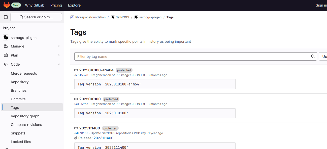
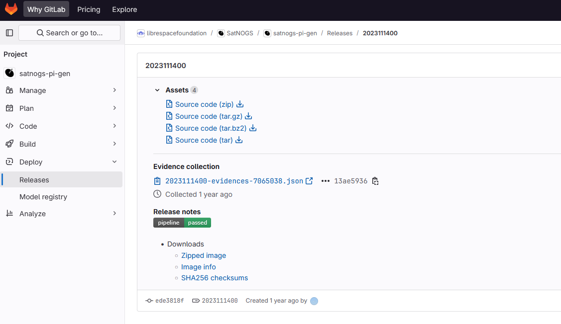
Each release will have four downloads. We only need to download the “Zipped Image”. Click on the word “Zipped Image” on the most recent release to download it. The file will take a few minutes to download. The other two files in the Downloads list are text files with information about the image that you can download if interested.
3. While the above is downloading, open a new tab and go to: https://www.balena.io/etcher/ Download the balenaEtcher software from the homepage selecting your operating system version.

Navigate to the “Downloads” folder on your computer. Find the balenaEtcher installation package and double-click it. Follow the instructions to install the program.

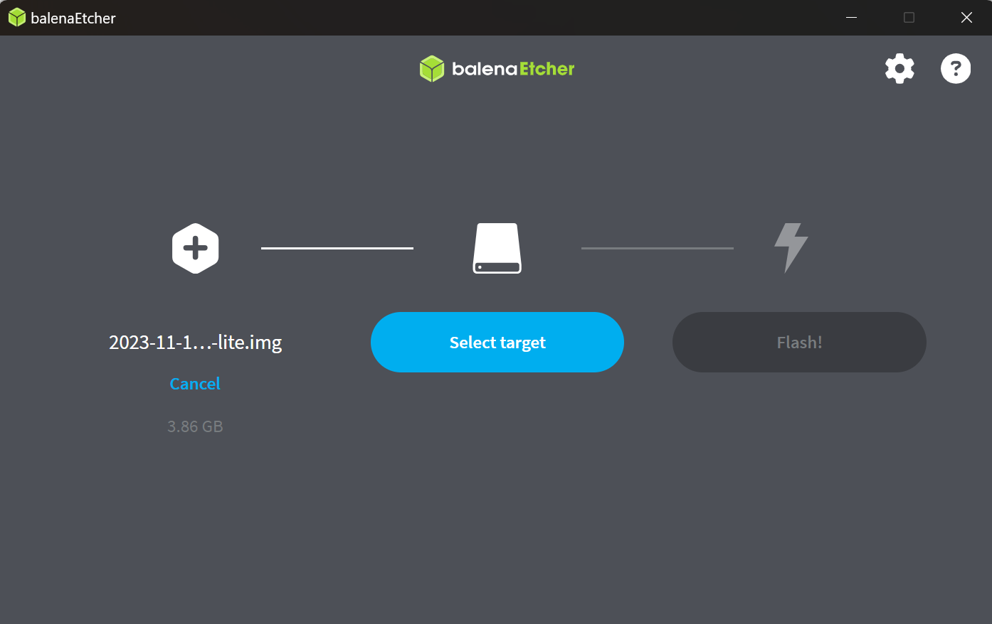
Open the balenaEtcher application. There are three stages of flashing the image in the SD card, first select the file, second select the destination to be copied and finally flashing. Select the first option, navigate to the zipped image you have download on the step 2, and you should see a file ending in .img appear.
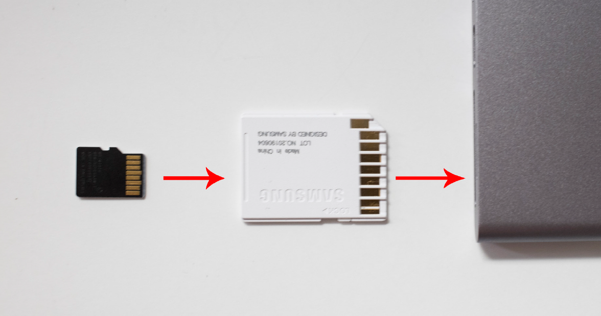
Insert the microSD card (Part 3) into the included SD Adapter, and then insert the SD Card (upside down) into the USB SD Card Adapter (Tool 9) connected to the Laptop (Tool 8).
Selecting the second step of the balenaEtcher application the SD Card will appear on the Desktop, and likely be called “Untitled” or “NO NAME”.
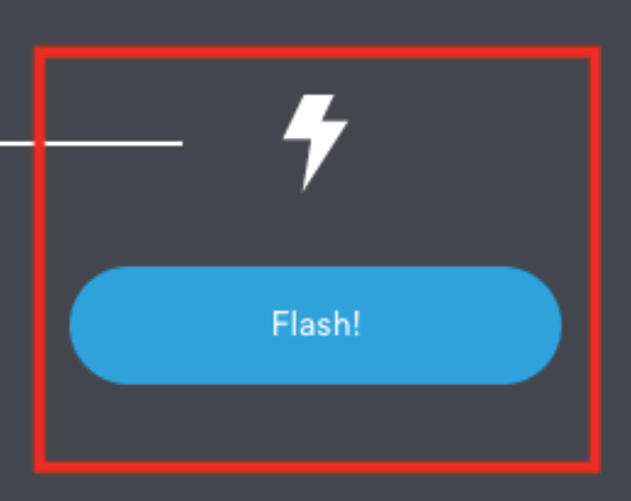
Click the blue
Flash!button.
Type in the password you use to log in to the computer, and click OK.
Wait a few minutes for it to flash (copy) the SatNOGS software onto the microSD card.
Wait until you see “Flash Complete!”
Remove the microSD Card and SD Adapter from the computer.
Install the PoE HAT and MicroSD Card
The SatNOGS Kit uses a Raspberry Pi as the Single Board Computer to control the ground station. Before we can install the Raspberry Pi in the Enclosure, we need to physically install two essential peripherals: a PoE HAT and an SD Card. PoE HAT stands for Power Over Ethernet Hardware Attached on Top. It allows the Raspberry Pi to receive power from the Ethernet Cable that is also being used to connect the Pi to the Internet. This simplifies the design of the ground station by only having to run one cable from inside the building to the ground station on the roof. We will also install the MicroSD card that we prepared in the previous section.
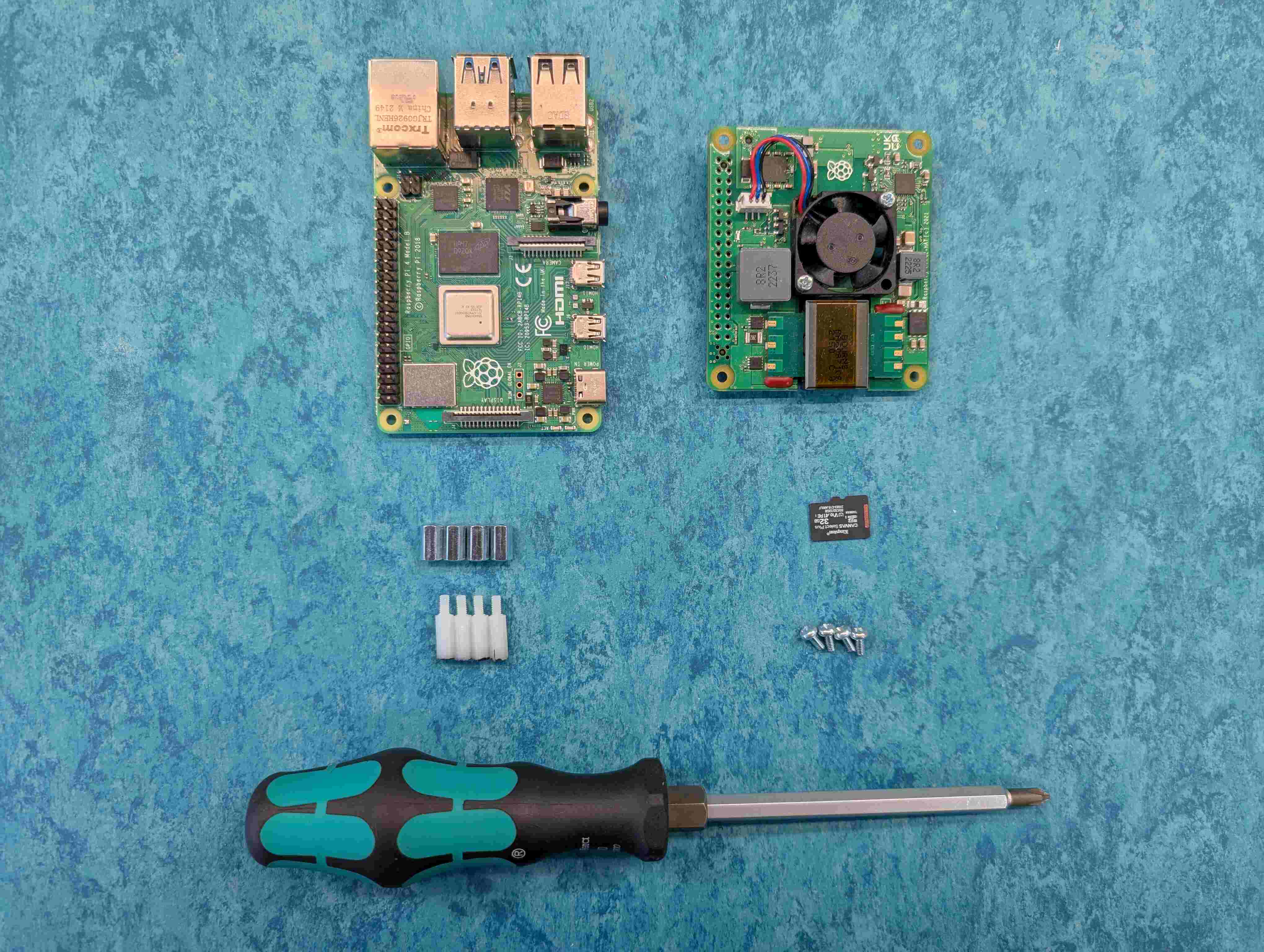
Parts
Raspberry Pi 4
PoE HAT
SD Card
Screws
Stand-offs
Tools
Screwdriver set
Find a clean, well-lit surface to work on. Take the Raspberry Pi and the PoE HAT out of their packaging. From the Screwdriver Set, take out the handle and insert a suitable bit for the screws.
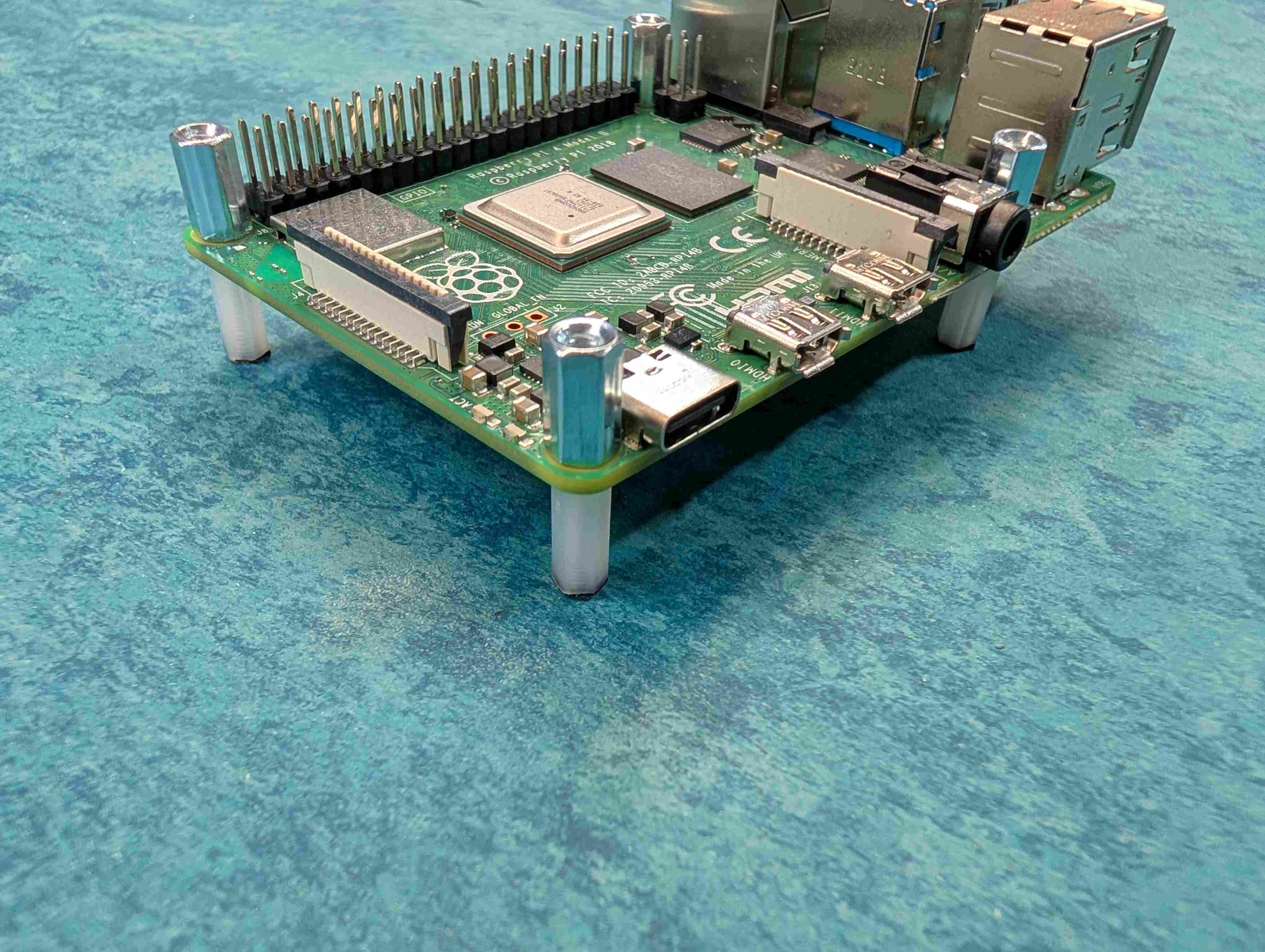
The PoE HAT comes with a bag of plastic stand-offs and metal stand-offs. Flip the Raspberry Pi over and insert one of the plastic stand-offs into one of the four holes in the Pi.
Holding the screw with your finger, flip the Raspberry Pi back over and start screwing on one of the stand-offs with your fingers. Repeat with the three other holes on the Raspberry Pi.
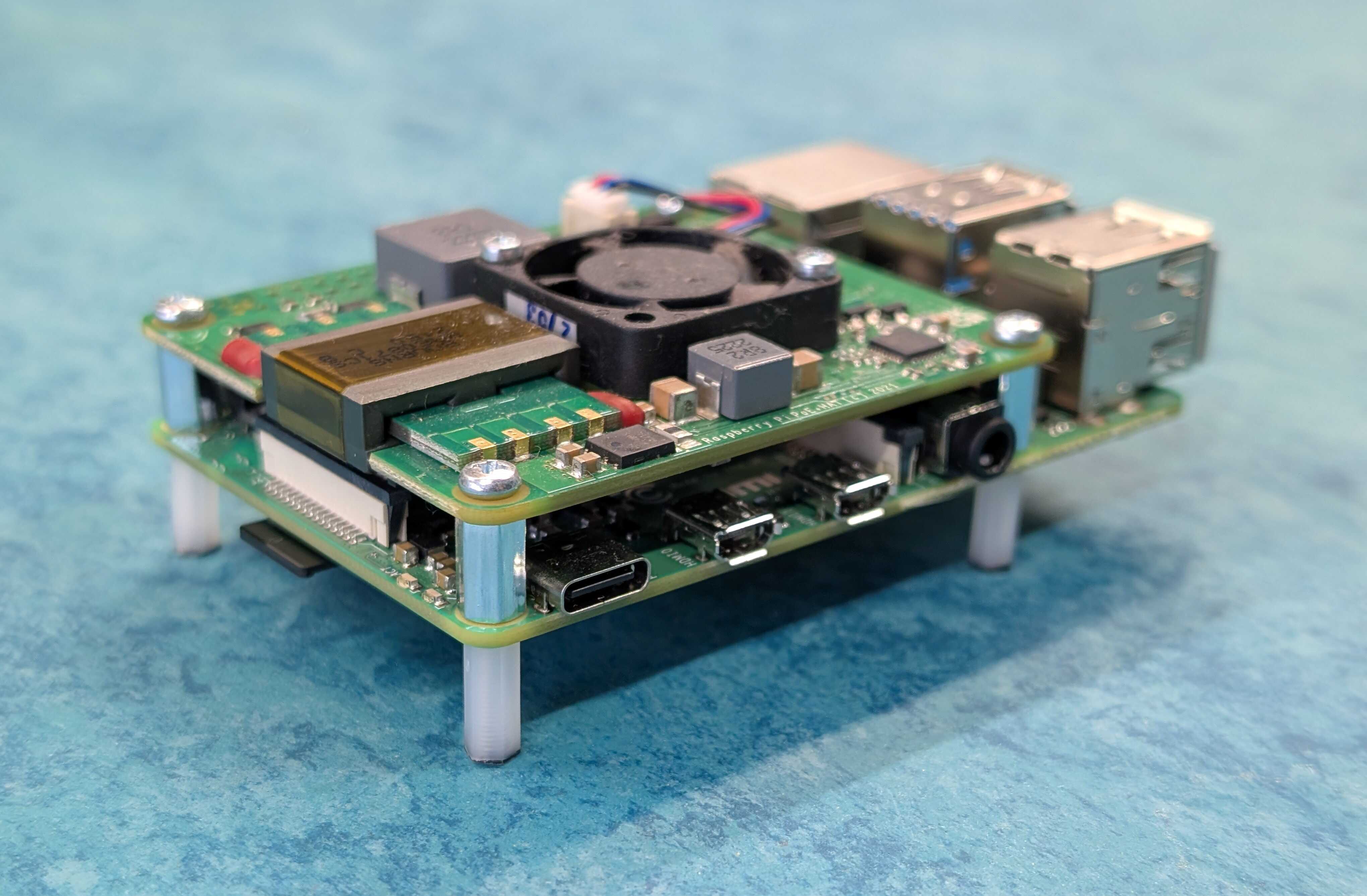
Carefully line up the GPIO (metal pins) on the Raspberry Pi with the matching receptacles on the PoE HAT and push down using both hands to apply even pressure.
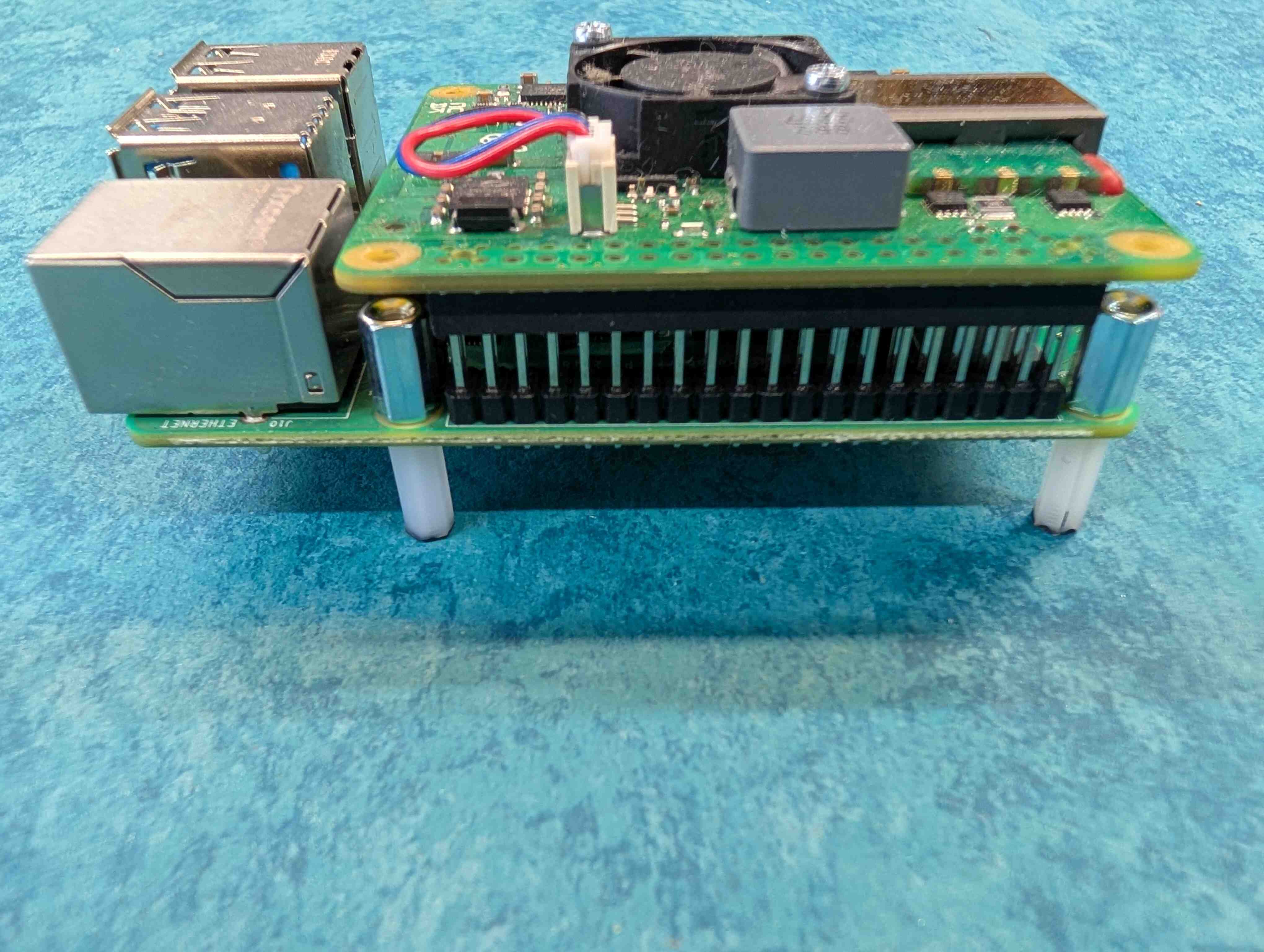
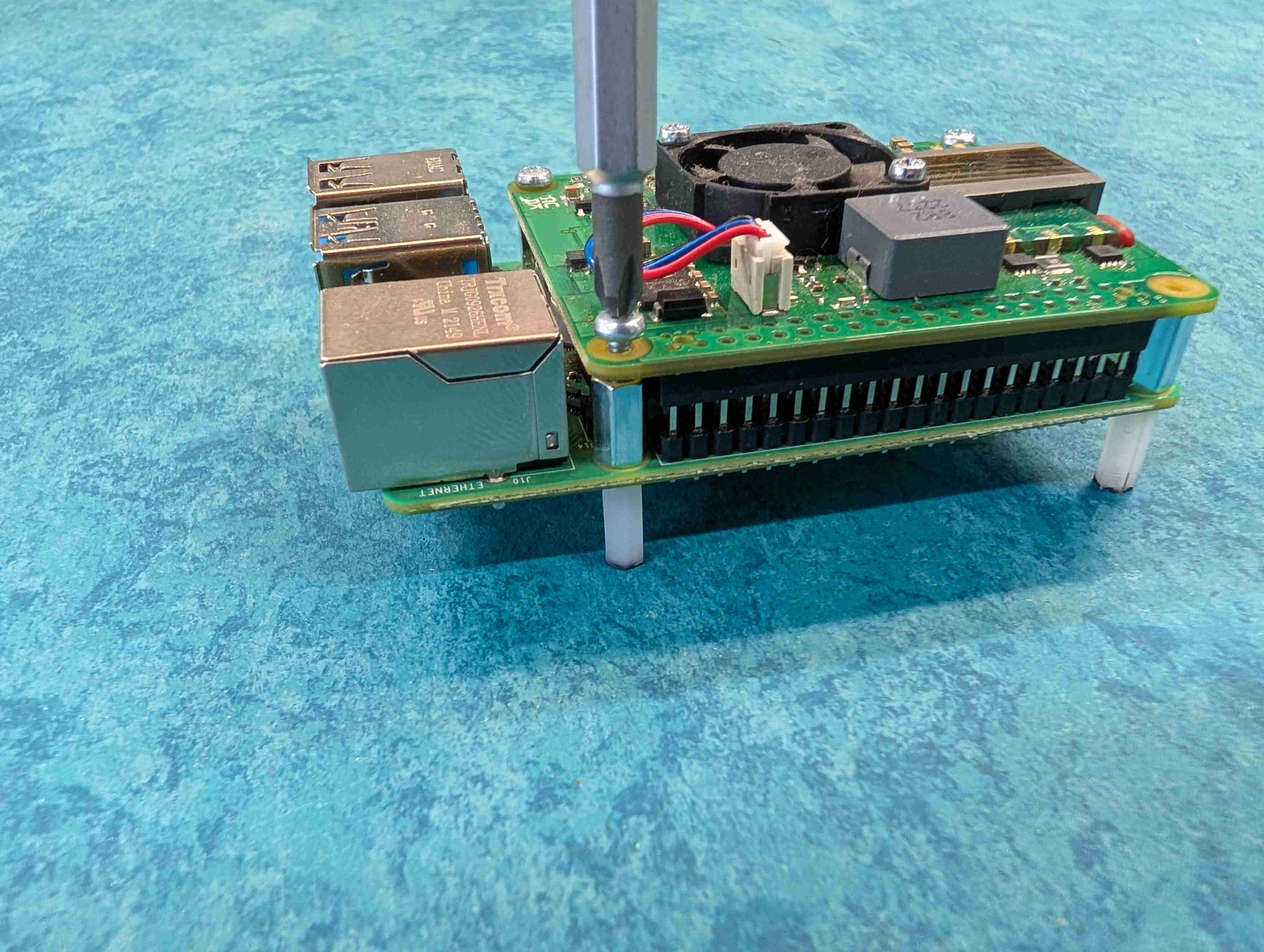
Using the screwdriver, screw the remaining four small screws into the four holes on top of the PoE HAT.
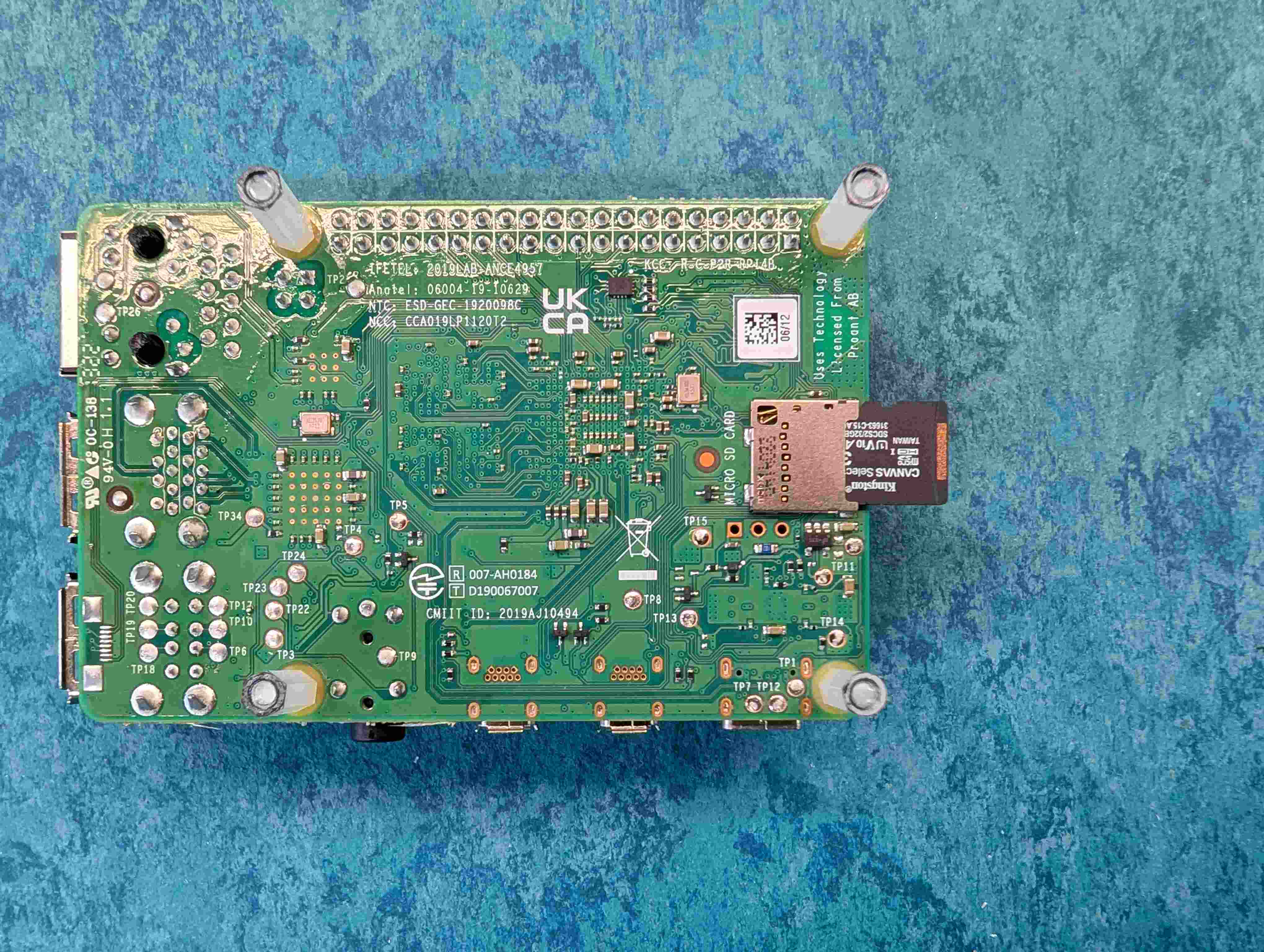
Flip the Raspberry Pi over and insert the MicroSD Card into the MicroSD Card slot on the Raspberry Pi.
Assemble the Enclosure
The enclosure is the protective shell that houses the core parts of your SatNOGS station. In this section, we’ll guide you through installing the Raspberry Pi, software-defined radio (SDR), and cables within the enclosure. By the end the unit will be ready to be mounted on the mast and connected to the other parts of the station .
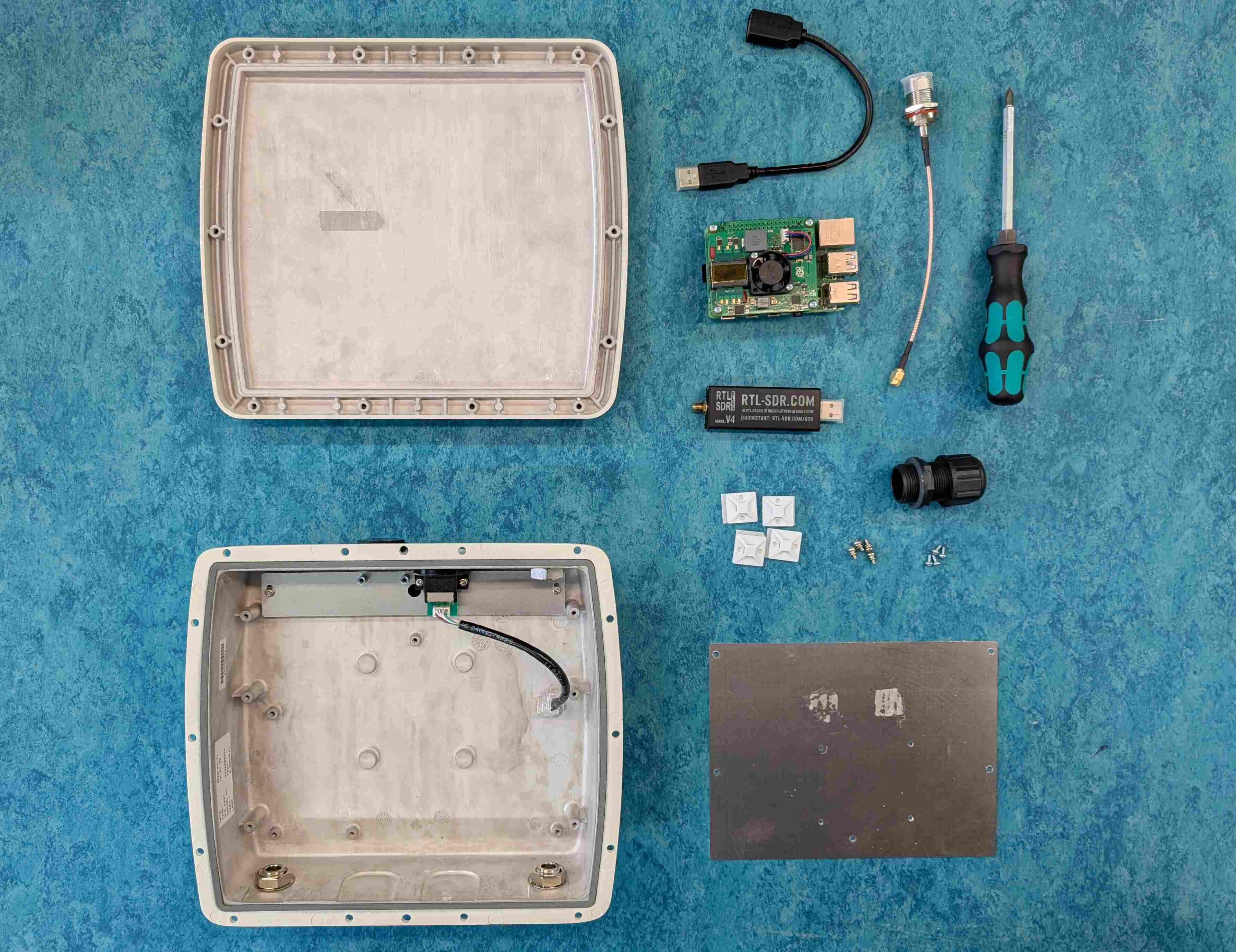
Parts
1,2,3. Assembled Raspberry Pi
USB Extension Cable
Software Defined Radio (RTL-SDR v3)
Pigtail (SMA to N-type)
Enclosure (Top, Bottom, mounting plate, screws, UTP Enclosure Connector)
Tools
Screwdriver set
ZipTies
ZipTies holders
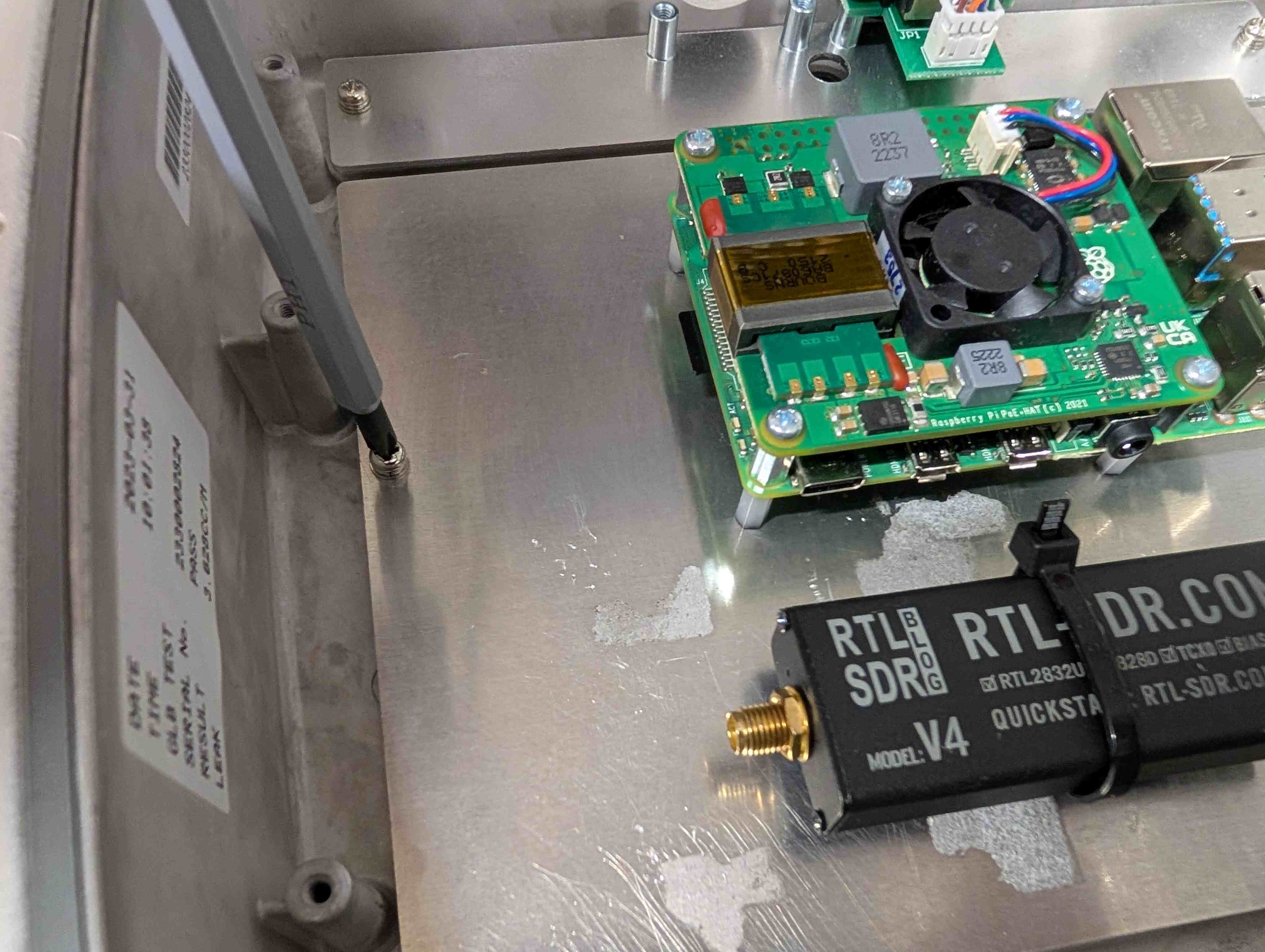
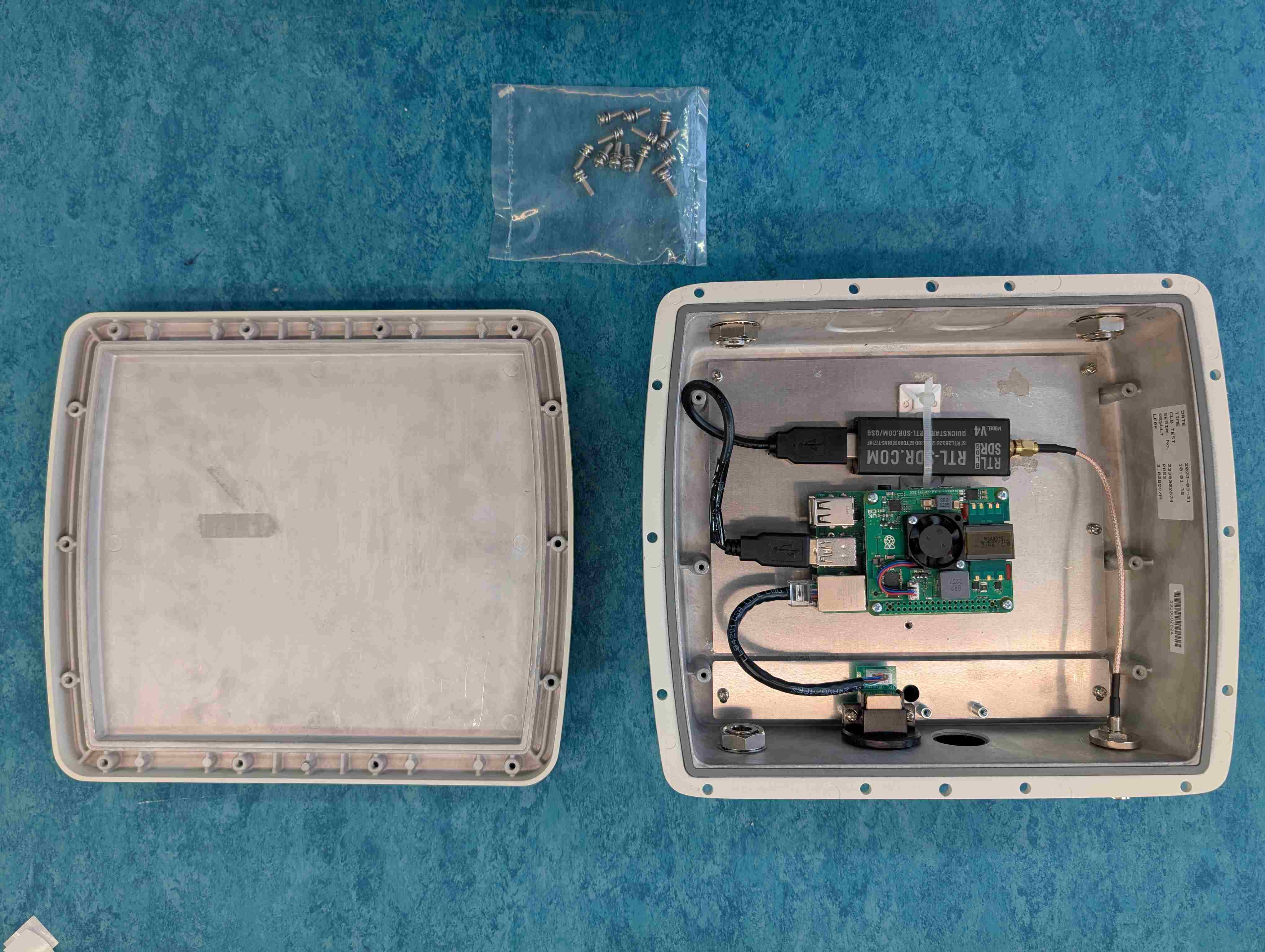
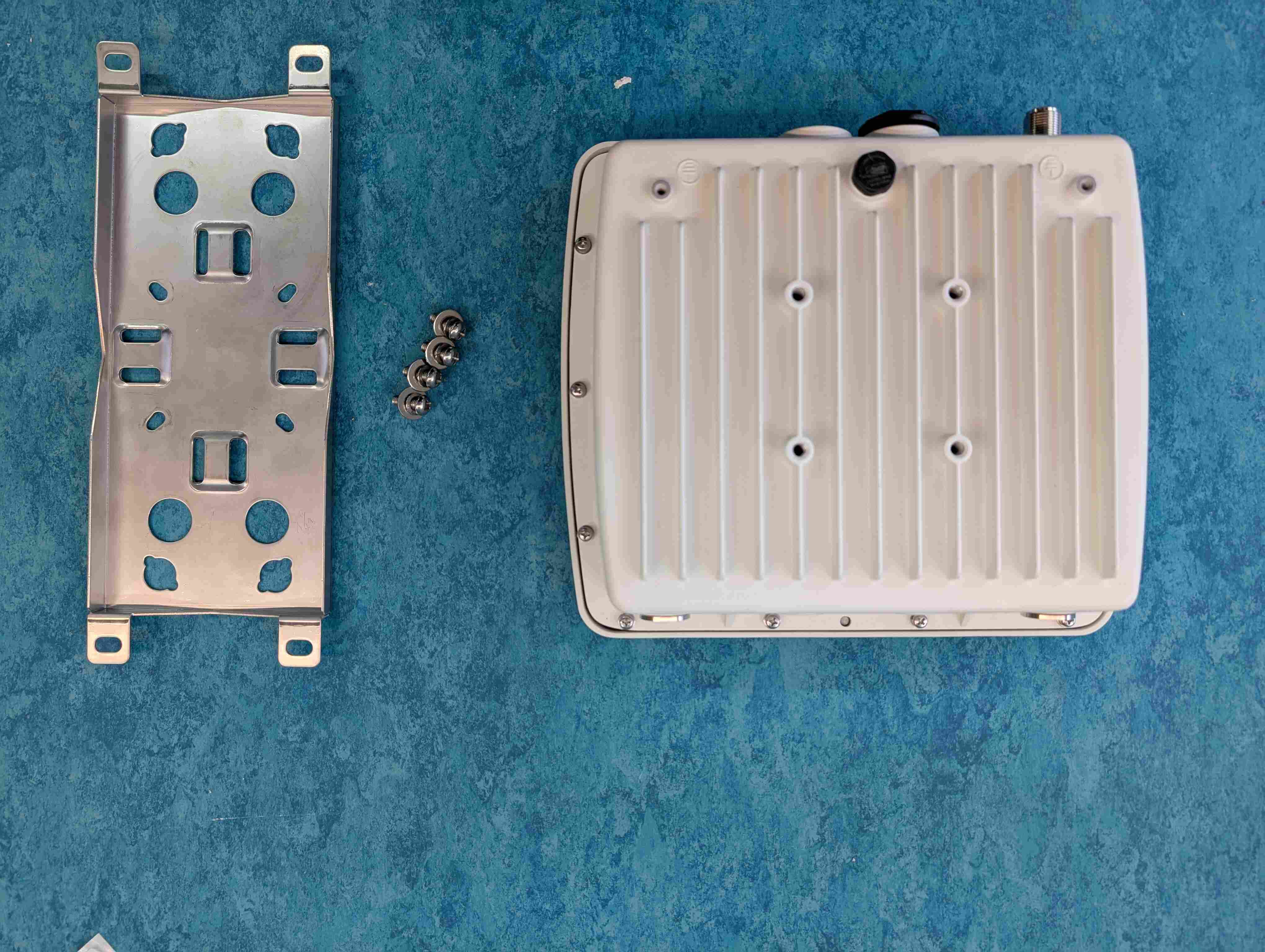
Remove the mounting plate from the plastic bag with the four screws. Orient the plate in front of you so that the two holes in the corners being on the bottom. Stick the zip-tie holder at the location as visible on the photo.
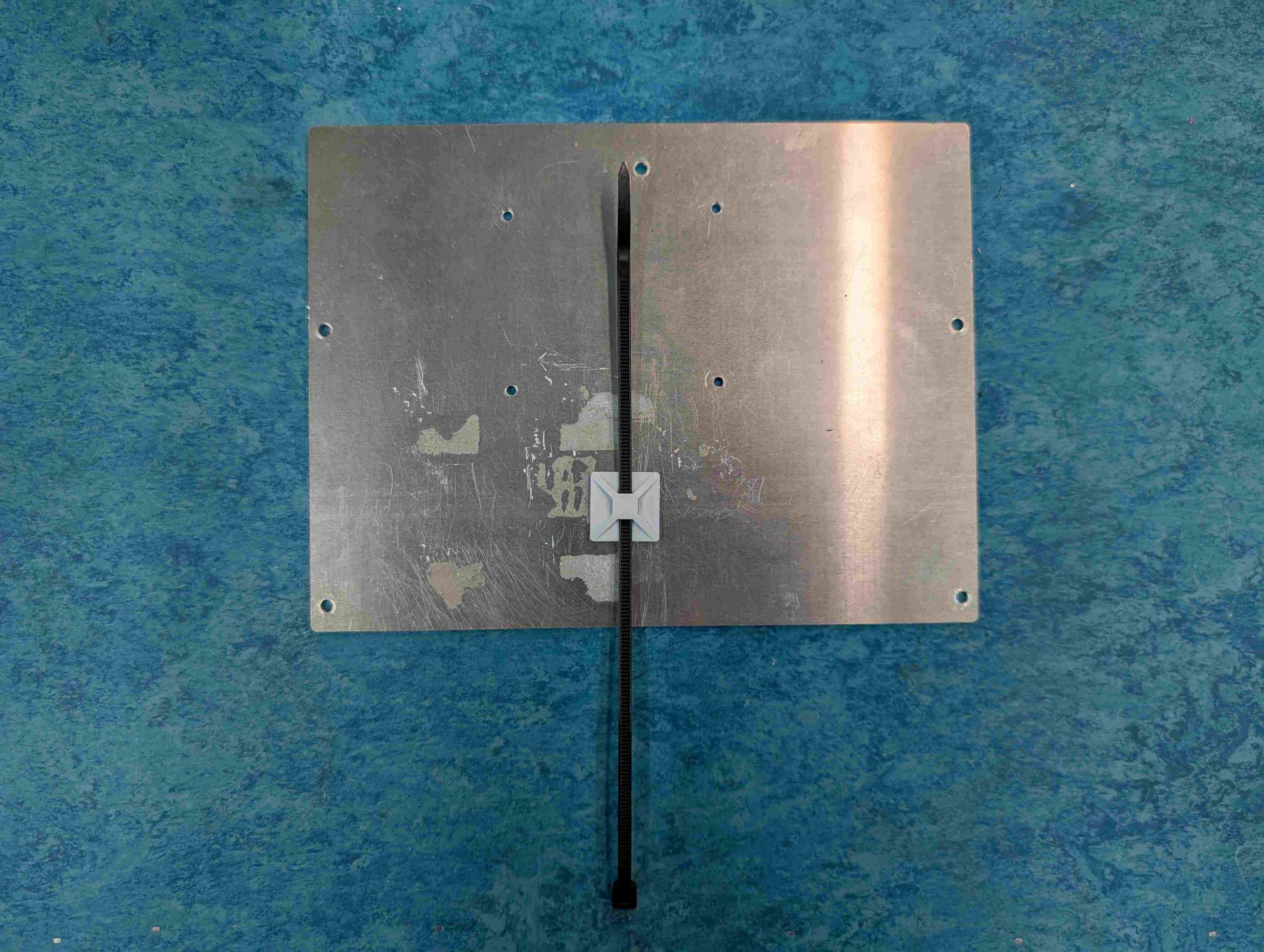
Take the ZipTie and feed it through the holes on the bottom side of the insert. Remove the Software Defined Radio (SDR) from its packaging and place the SDR with the word RTL-SDR being visible.
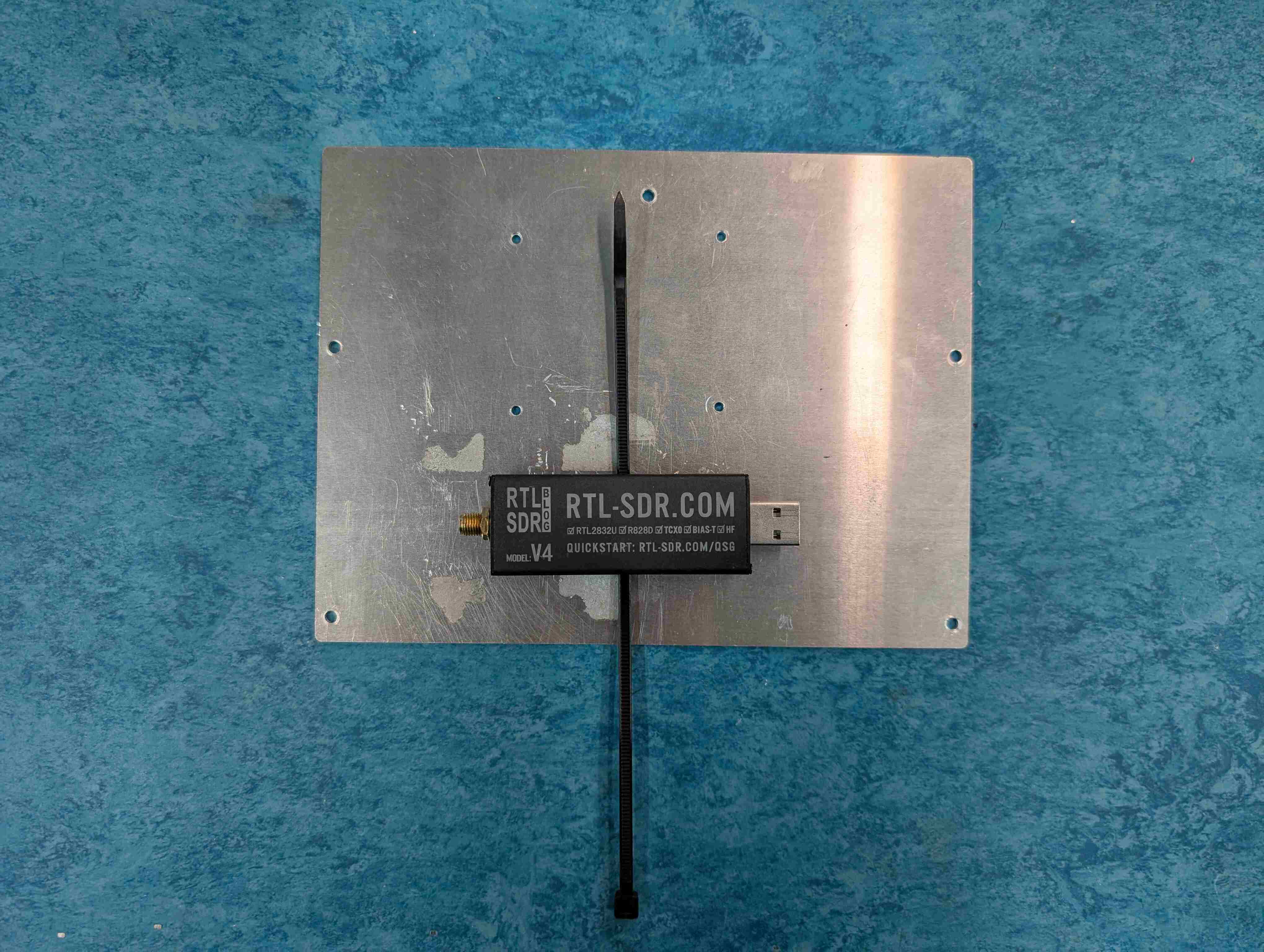
Pull the ZipTies through their eyes until tight. Snip off the excess with a pair of scissors.
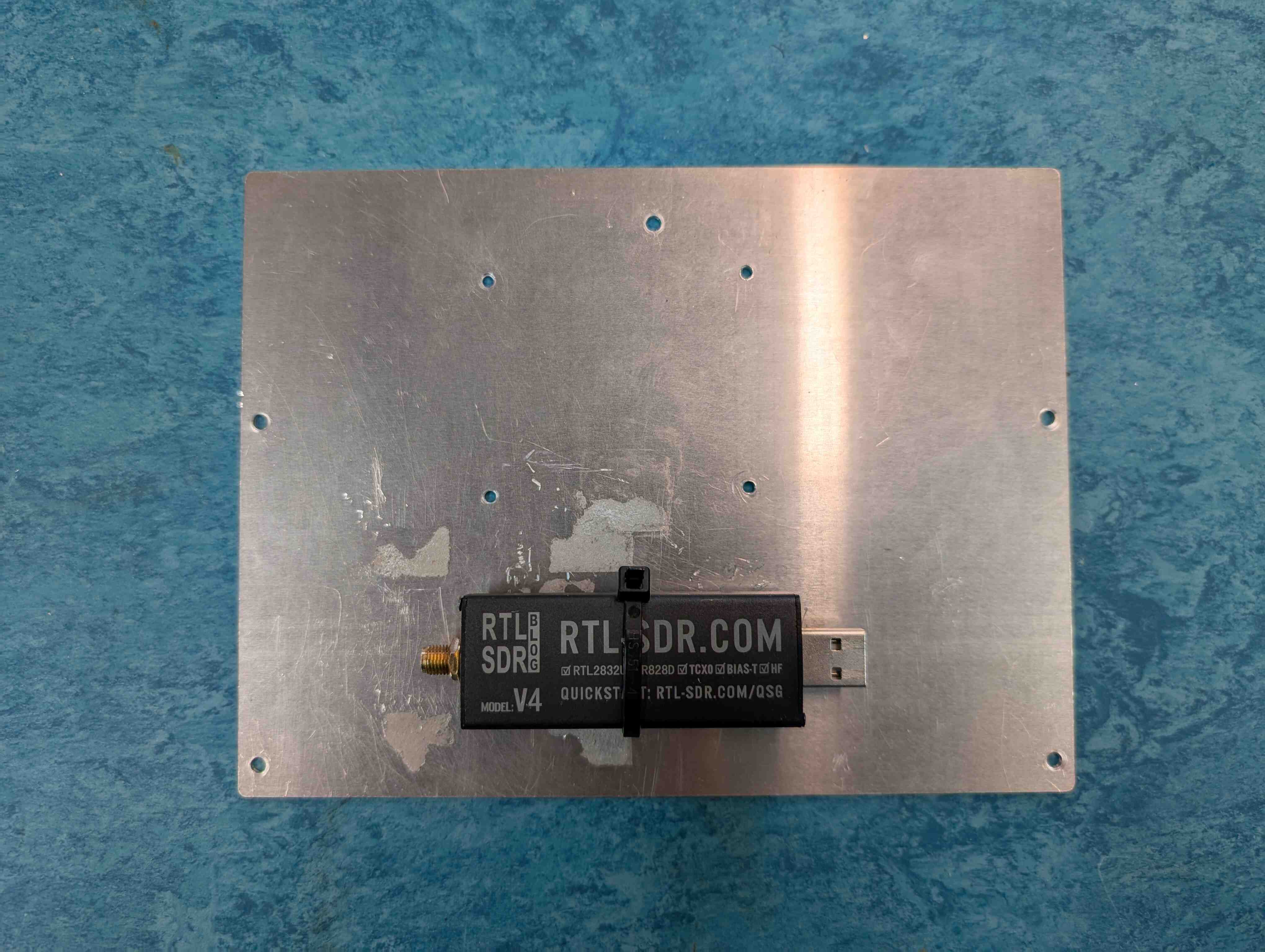
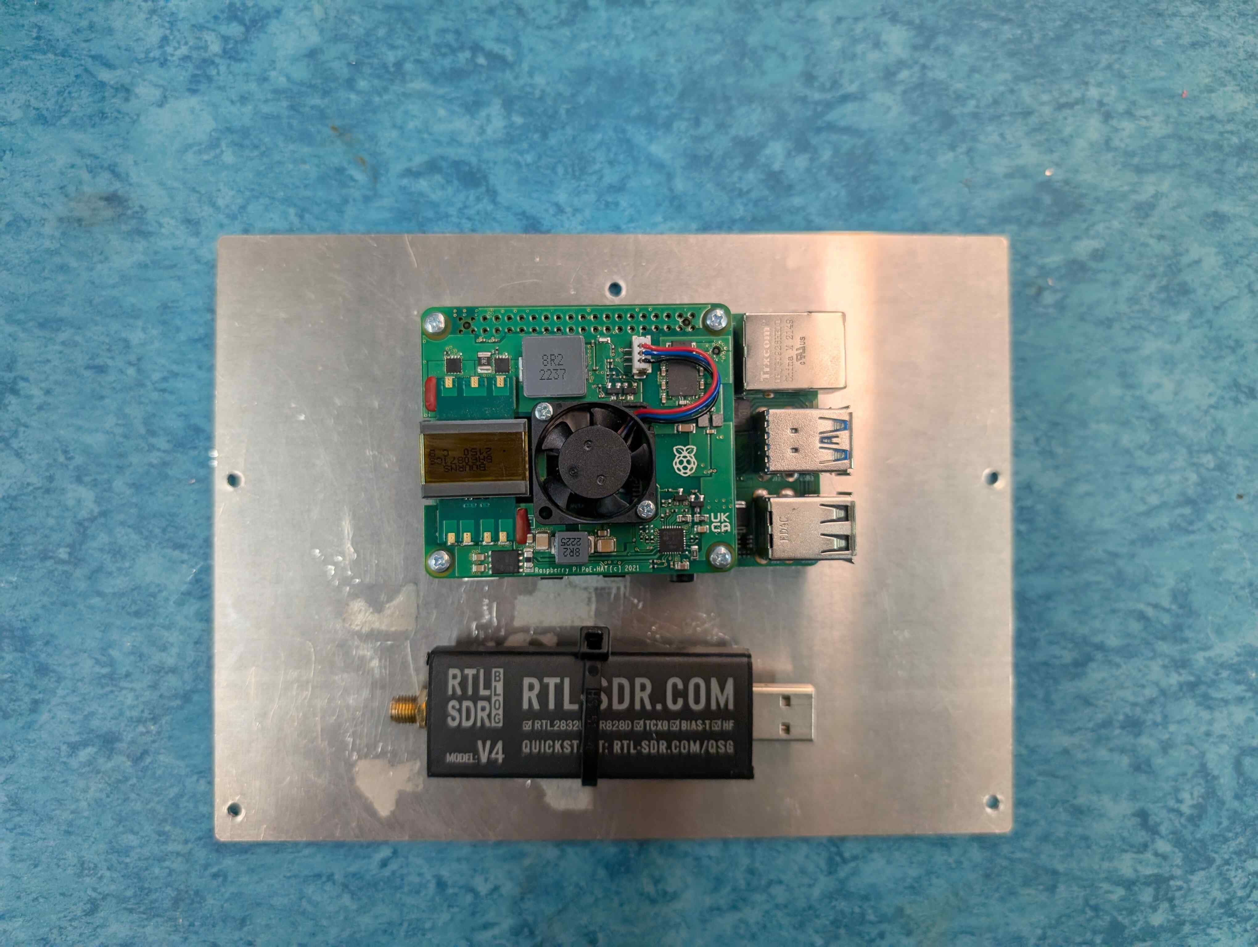
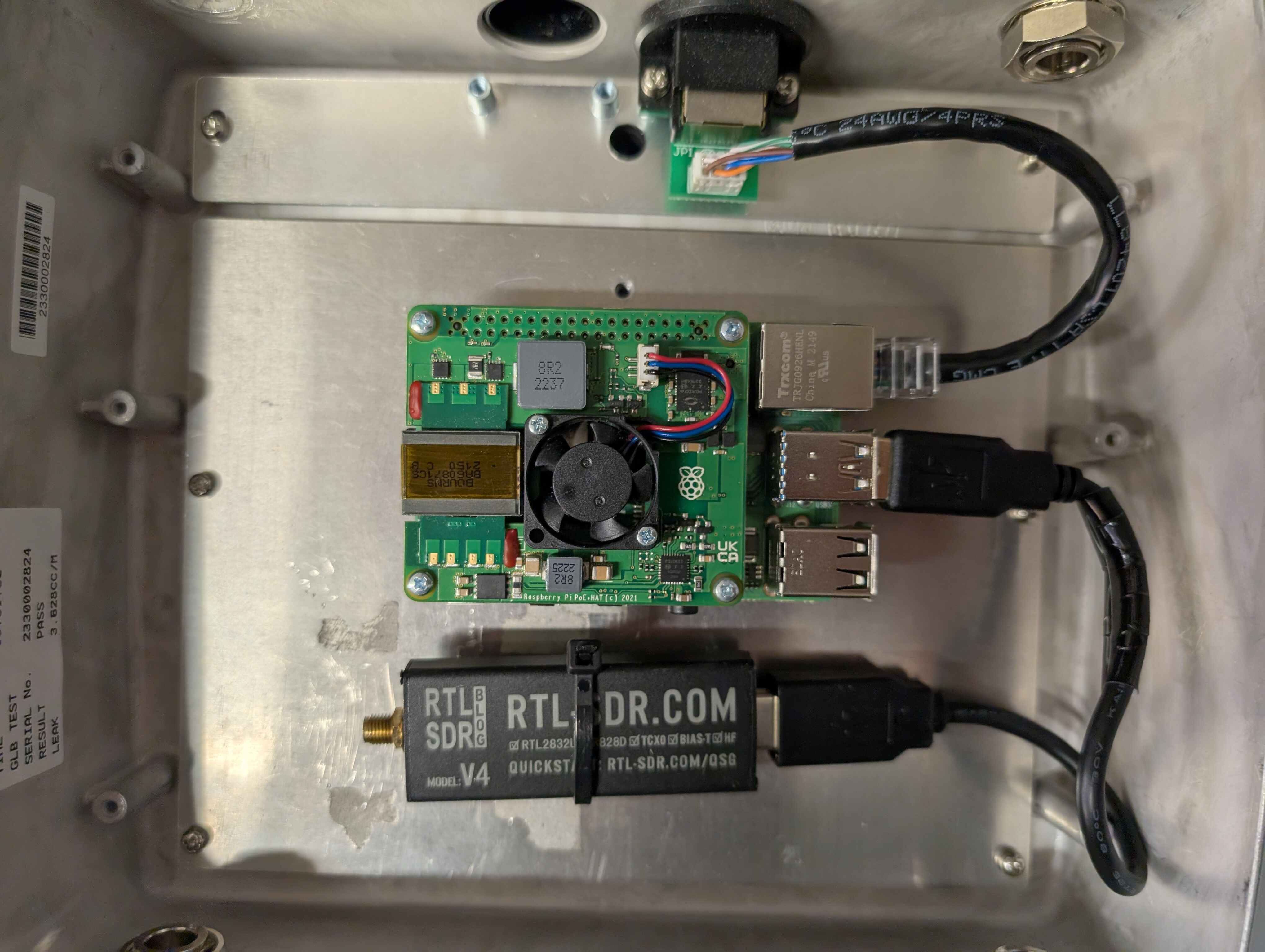
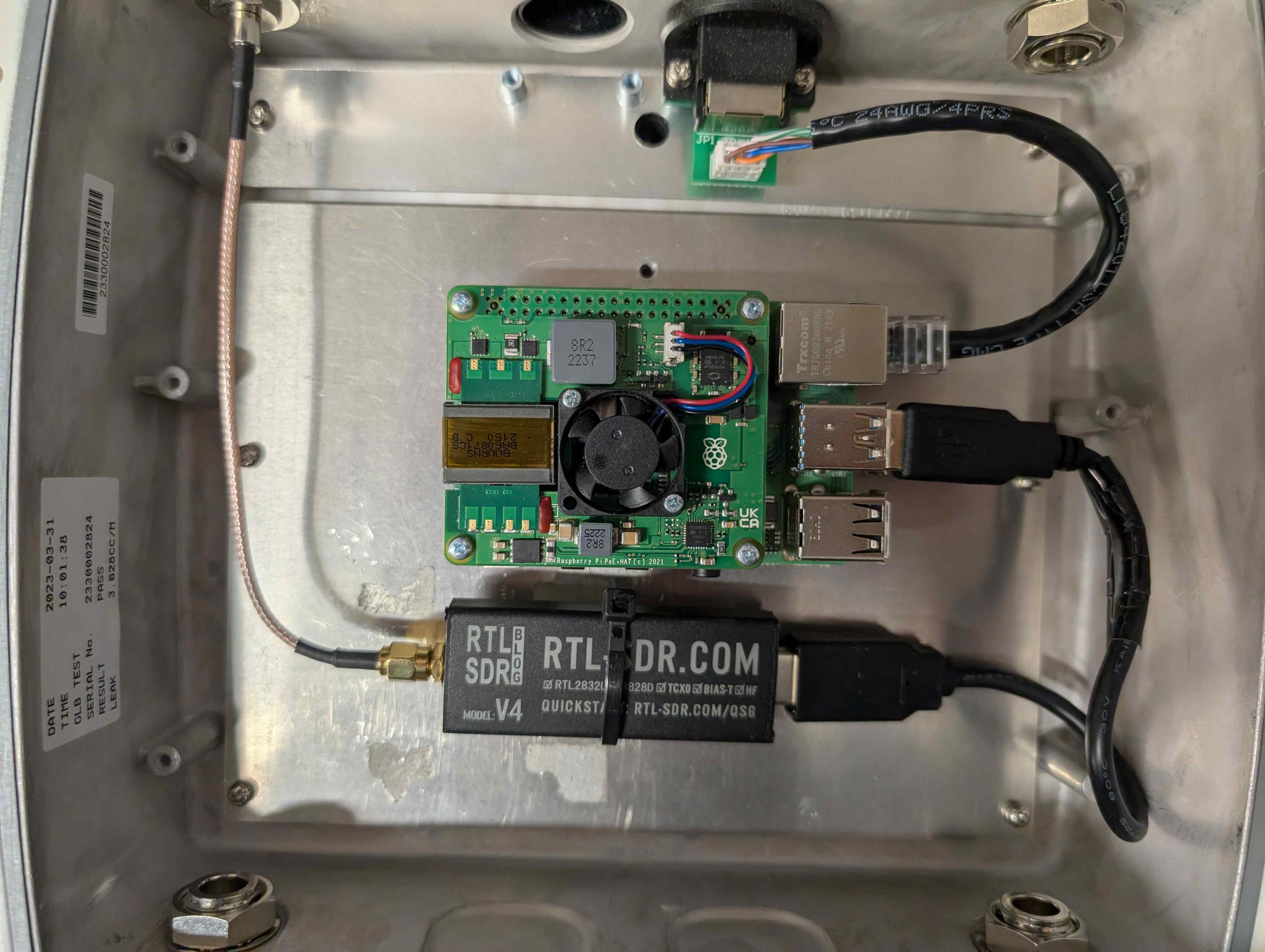
Place the Raspberry Pi with the USB ports at the right on the four holes upside from SDR. Flip the mounting plate and secure the Raspberry Pi on the mounting plate with the four screws in the mounting plate bag.
The mounting plate is ready to be installed in the enclosure. Place the mounting plate in the enclosure with the Raspberry Pi being close to the UTP port and the SDR at the bottom. Secure the plate with the five screws at the perimeter.
Connect the enclosure’s UTP cable to the Raspberry Pi port.

Take the USB Extension Cable and connect the straight end to the SDR. Connect the other end of the USB Extension Cable to the top USB 3.0 (blue) port on the Raspberry Pi.
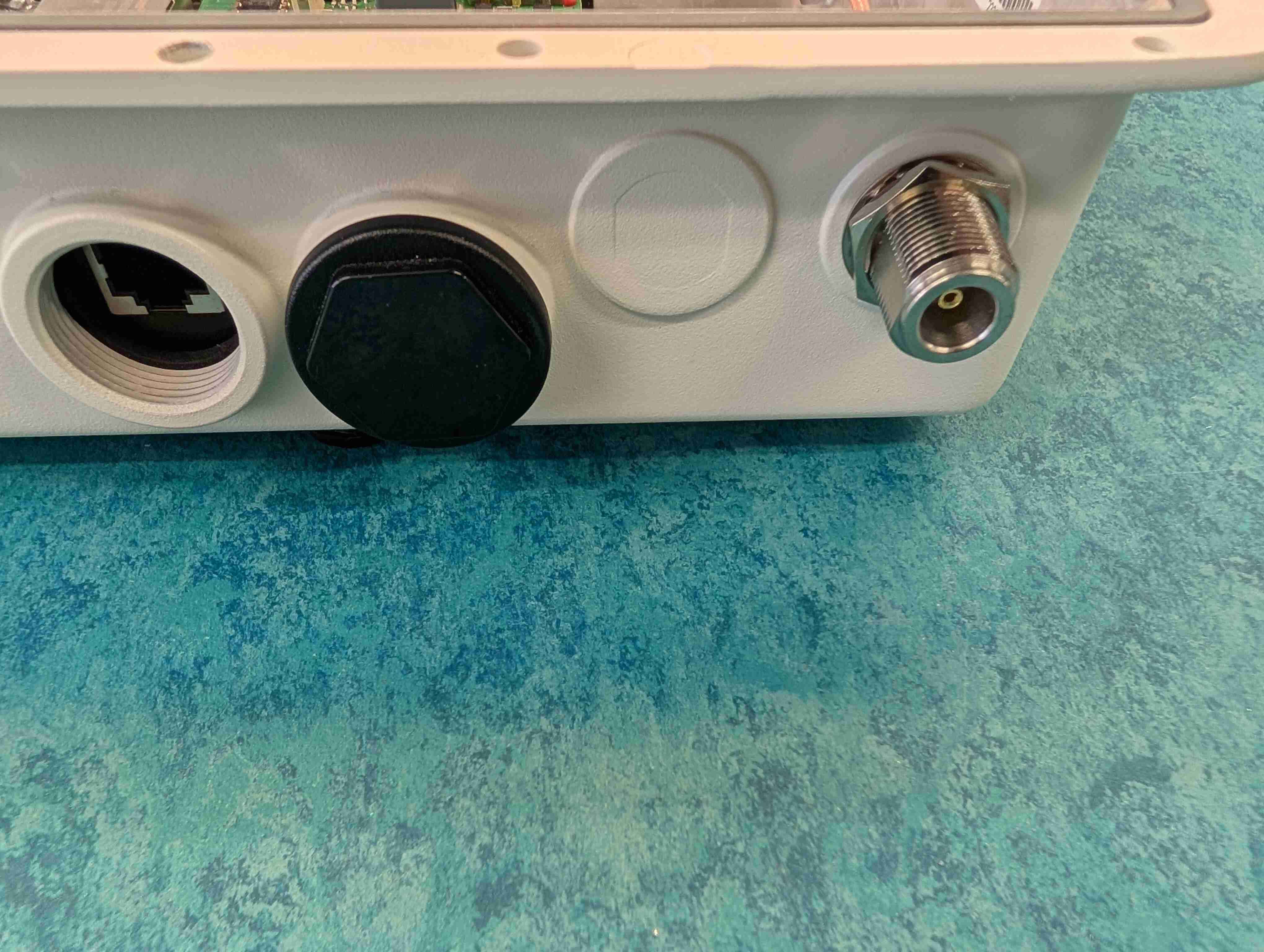
Remove the metal washer and retaining nut from the Type N connector on the RF Cable (SDR to Outside) and set them aside.
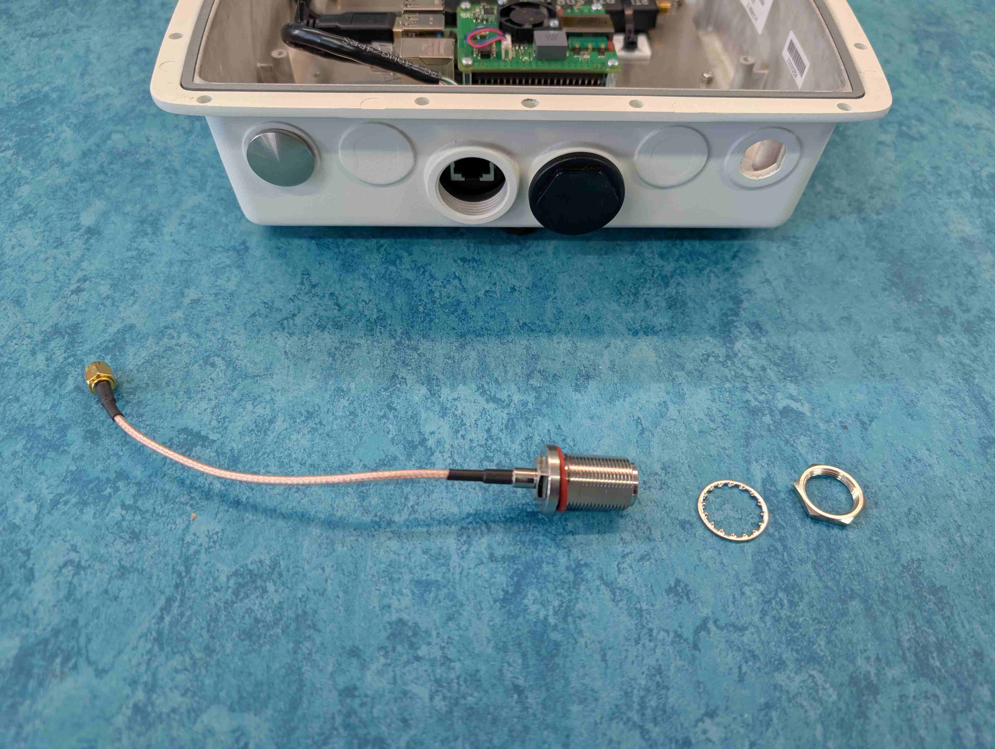
Line up the Type N Connector on the RF Cable (SDR to Outside) with the left hole on the top of the Enclosure, the one with the cap missing, and carefully push it through with your thumb.
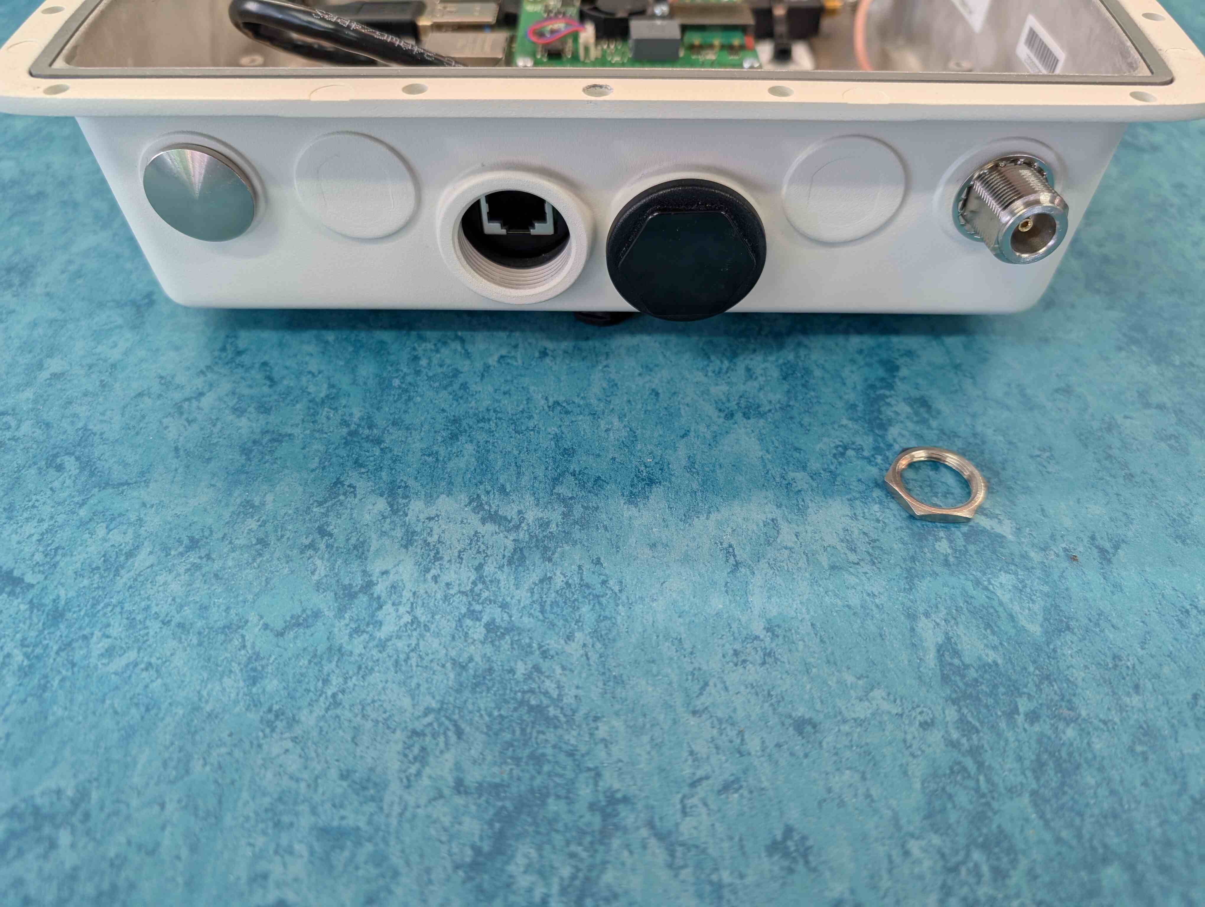
Working now on the outside of the Enclosure. Place the metal washer over the Type N Connector. While holding the Type N connector flush to the metal of the inside of the Enclosure, screw on the retaining nut as tight as you can with your fingers.
On the inside of the enclosure, connect the RF Cable to the SDR SMA.
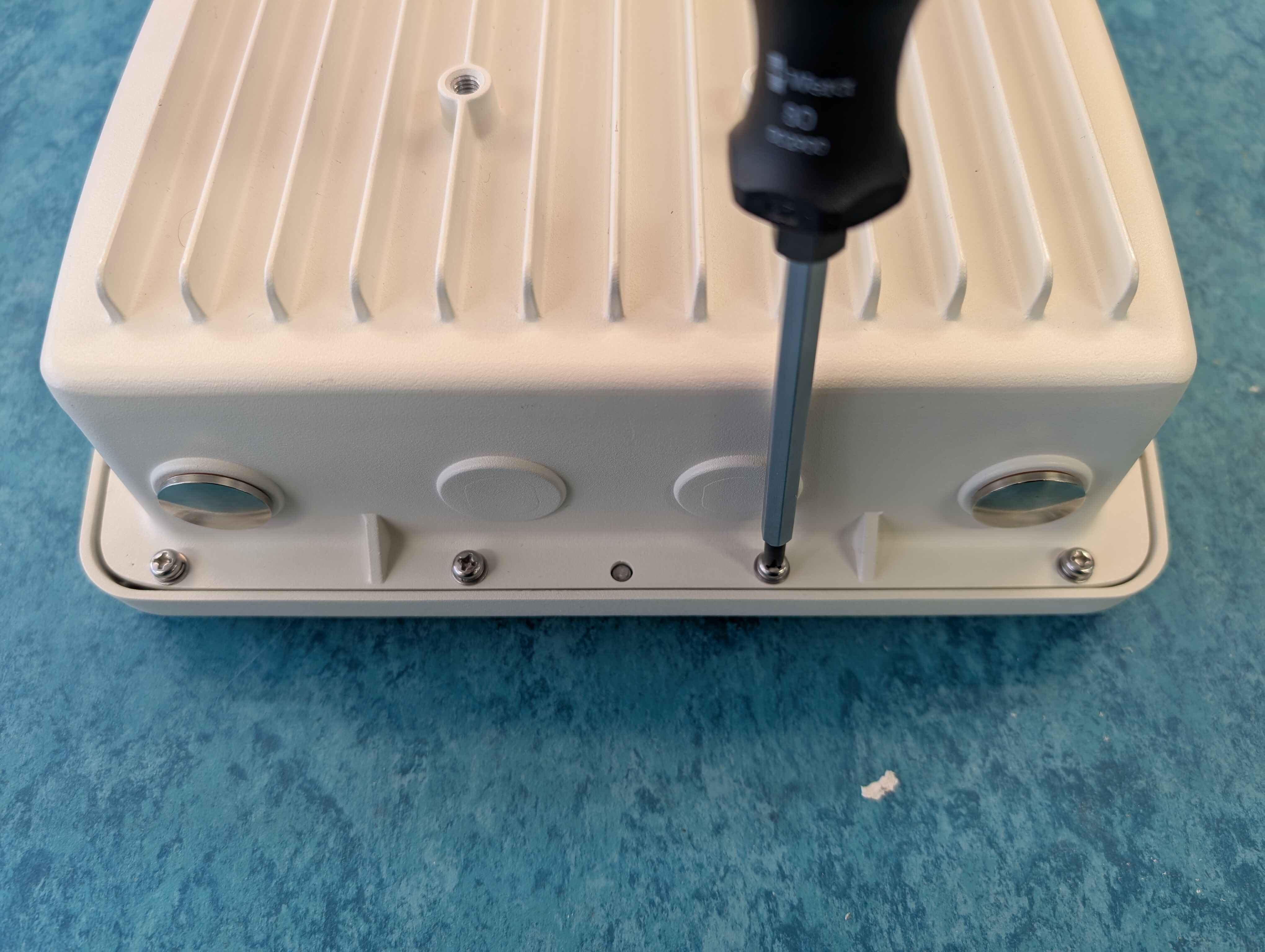
The enclosure is ready to be closed. Bring the top of the enclosure and the bag with the 14 screws
After ensuring the flange is in place, flip the top upside down and place the bottom on top of it. Start installing the screws to connect the two pieces.
Use the metal bracket for enclosure mounting on a mast. There are different options of bracket mounting but we will use as a baseline an horizontal placement.
Thread the Ethernet jack through the large hole on the bottom of the enclosure, and push the connector all the way in. Take the black plastic retaining nut you set aside and thread it back on finger-tight.
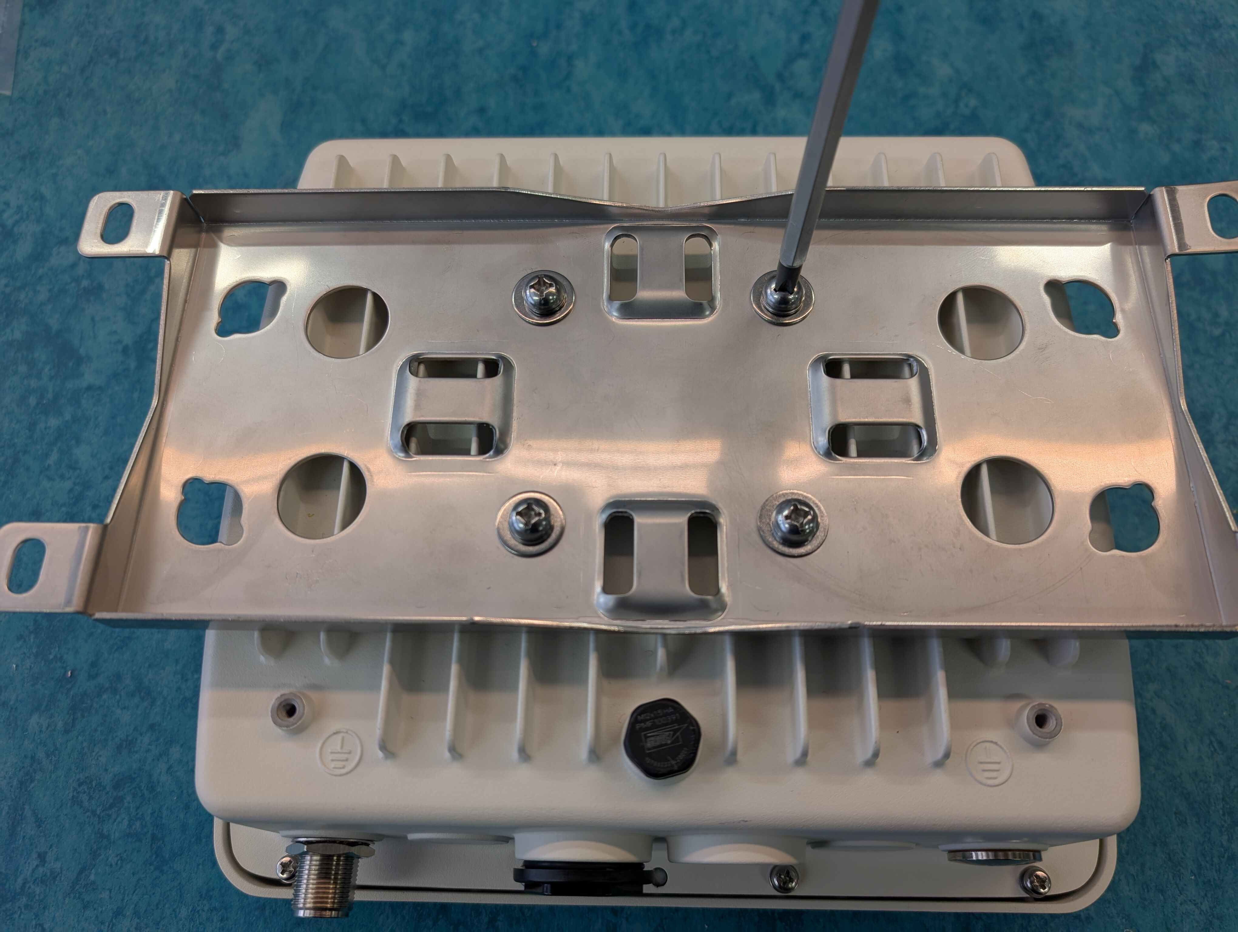
Align the four holes as in the image below and secure the bracket to the enclosure with the four screws.
Assemble the Antenna
The ear of your SatNOGS station is its antenna, which captures the radio signals transmitted by satellites as they pass overhead. This particular antenna is designed to receive signals in the 70cm band (400-470 MHz), a range used by amateur radio satellites.
Our kit features the Vinnant UR435/3-S antenna. It’s a special type called an omnidirectional antenna, meaning it can pick up signals from all directions - perfect for tracking satellites as they move across the sky.
This antenna is built in two parts:
Top Section: This holds the shorter antenna elements.
Bottom Section: This holds the longer antenna elements, and has a tuning ring to help you adjust the antenna for optimal performance.
Parts
10.A Antenna Body
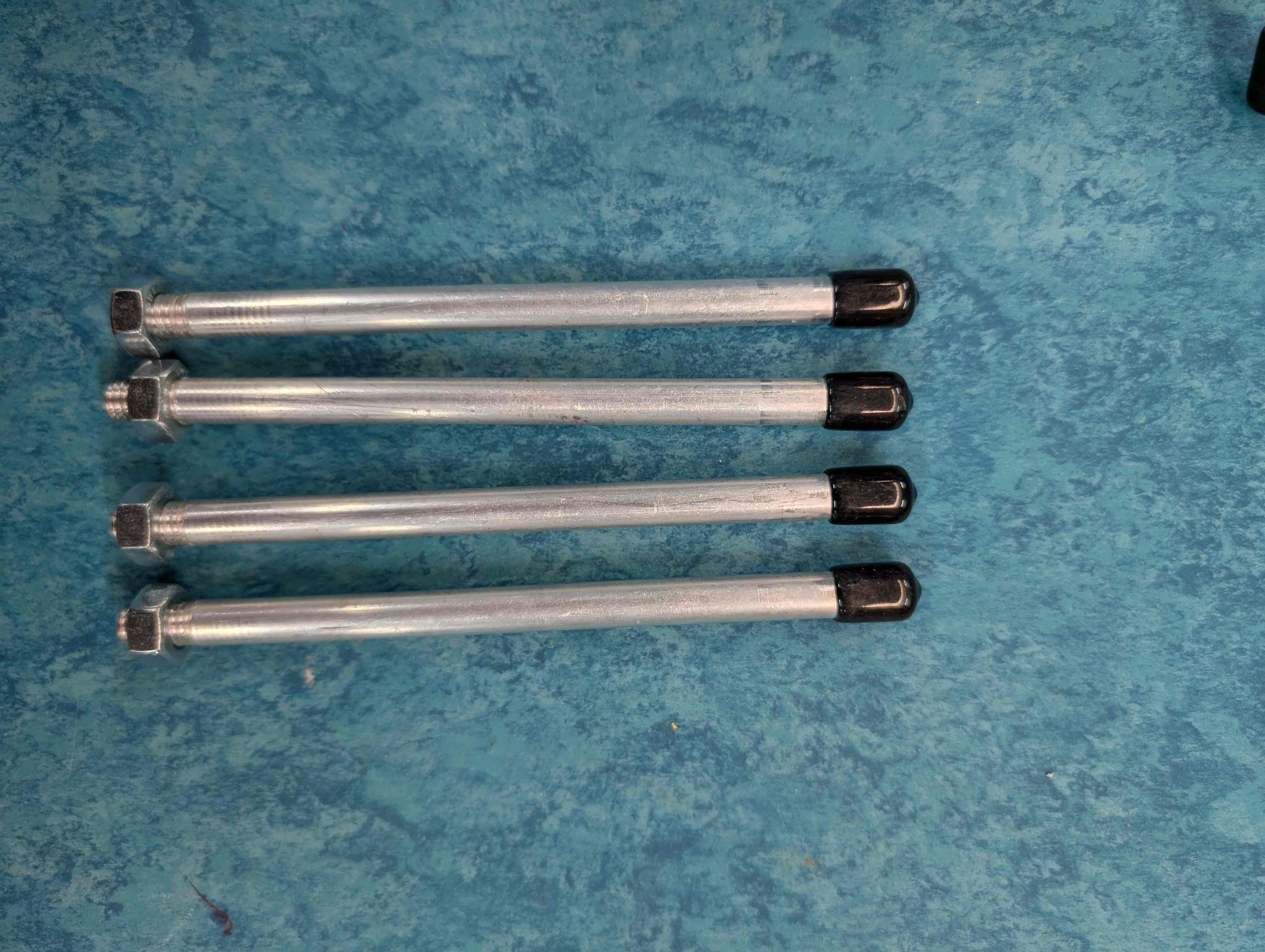
10.B 4 Short Elements
10.C 4 Large Elements
Tools
[ ] End Wrench
Allen Key
Place the short elements into the openings on the top section part one by one until it stops.
Screw tight small headless screws with provided Allen key.
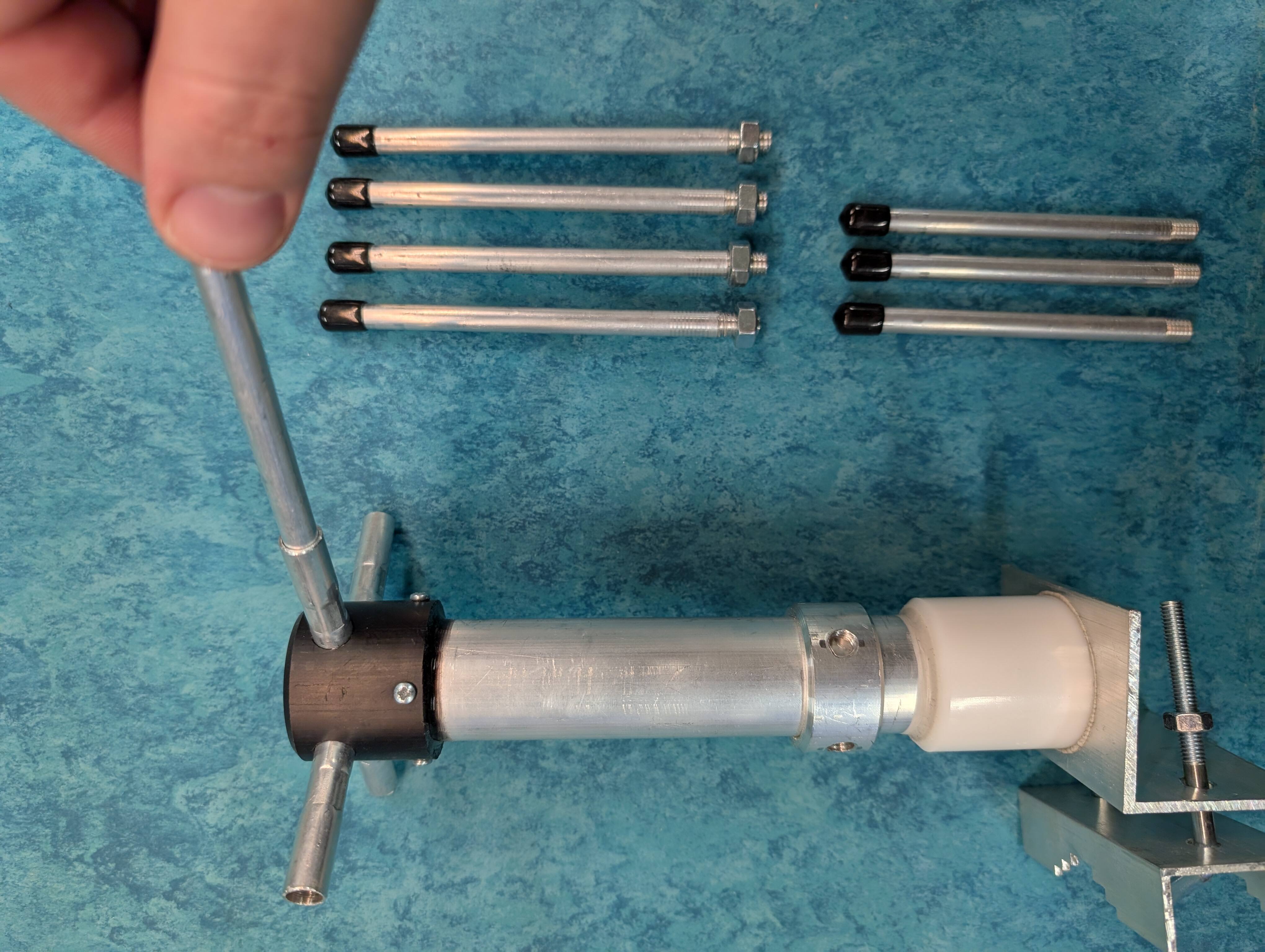
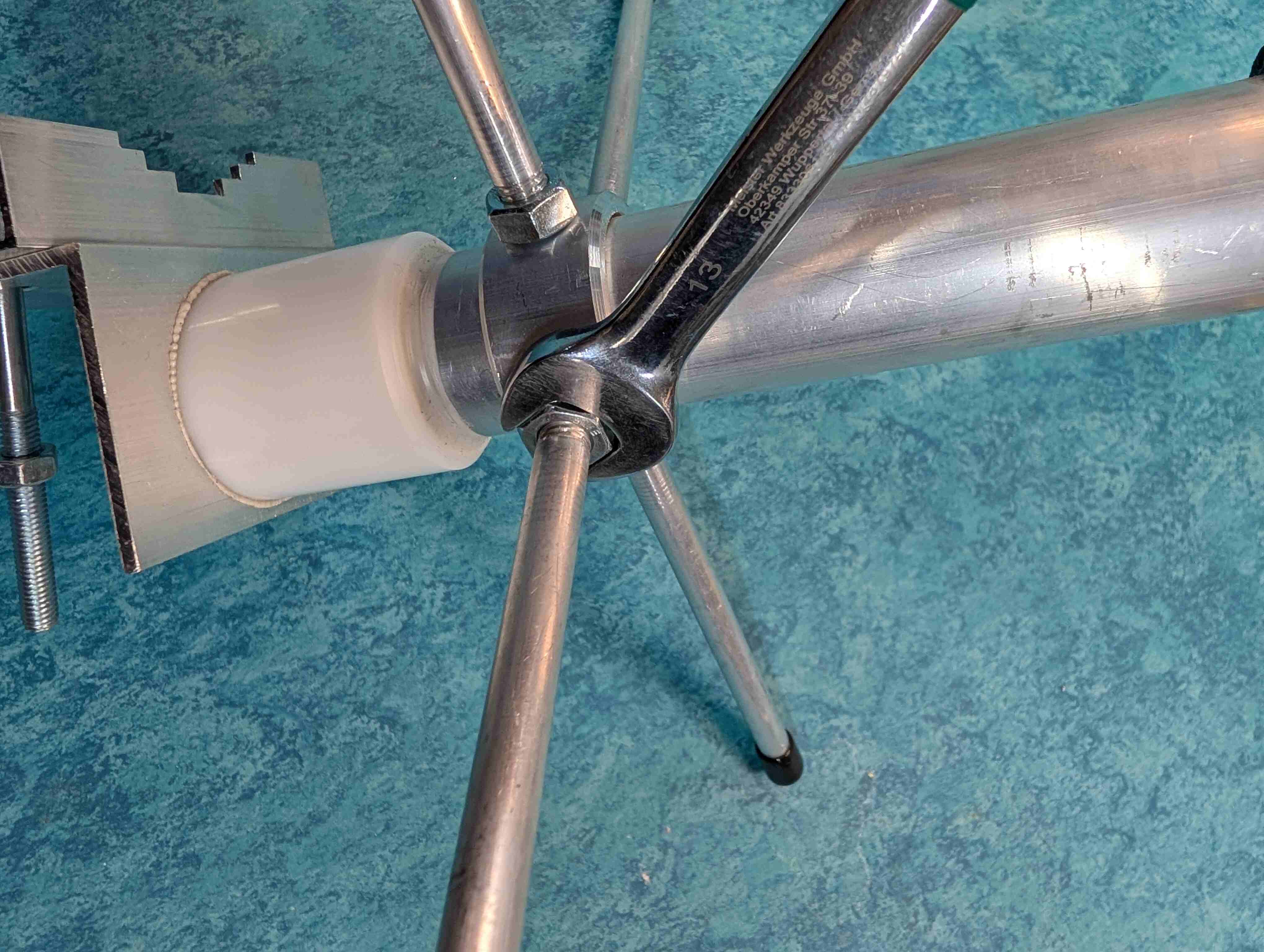
Make sure the nuts are at the very end of the threads before proceeding.
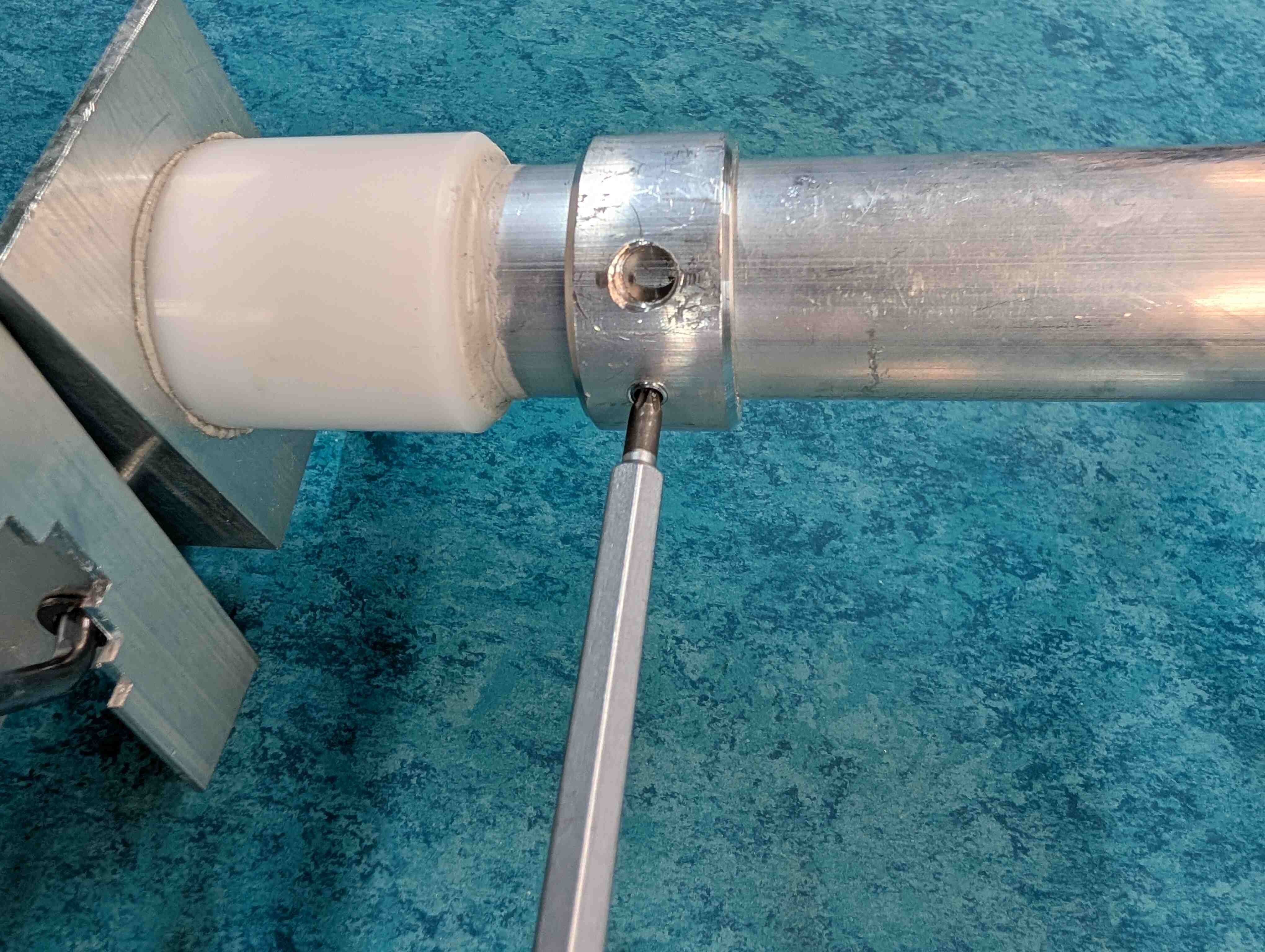
Screw the large elements on the bottom section tuning ring, near the bracket
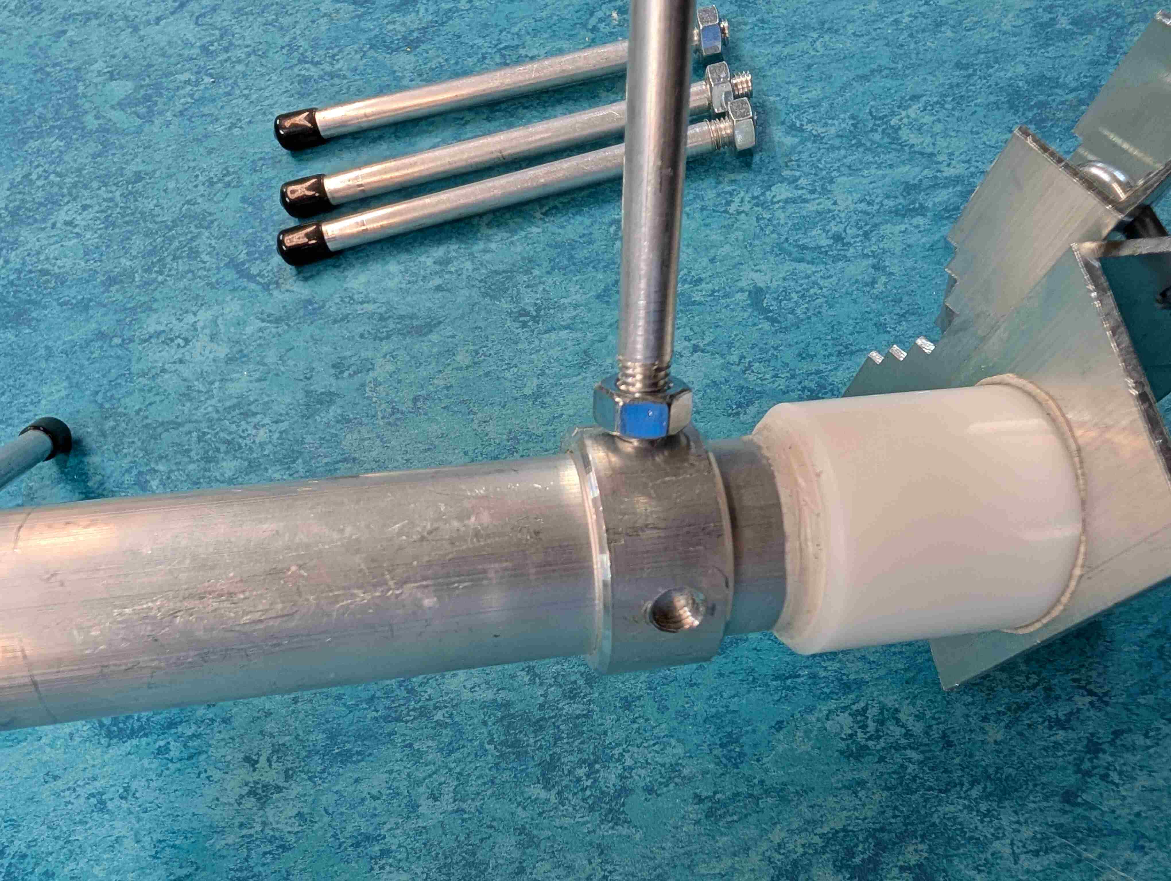
Lock the element from unscrewing by wing by counter locking the nut against the tuning ring, first hand tight the use the wrench key, turn the nut no more that 1/5 of the turn
Rooftop Install
Now that most of the components of the ground station are built, we need to prepare to install them in their permanent location. The most suitable location is likely the roof of a building as we want the antenna to be as high and free from possible interference as possible. There may already be a suitable pole or pipe on your roof that can function as the Mast (Part 12) for the ground station. The other preparatory steps are to find out how to run an Ethernet cable from the ground station on the roof to inside the building where it can be plugged into a dedicated Ethernet port. In addition to requiring one Ethernet port inside the building, the station also requires one grounded power outlet to plug in the Power Over Ethernet Injector.
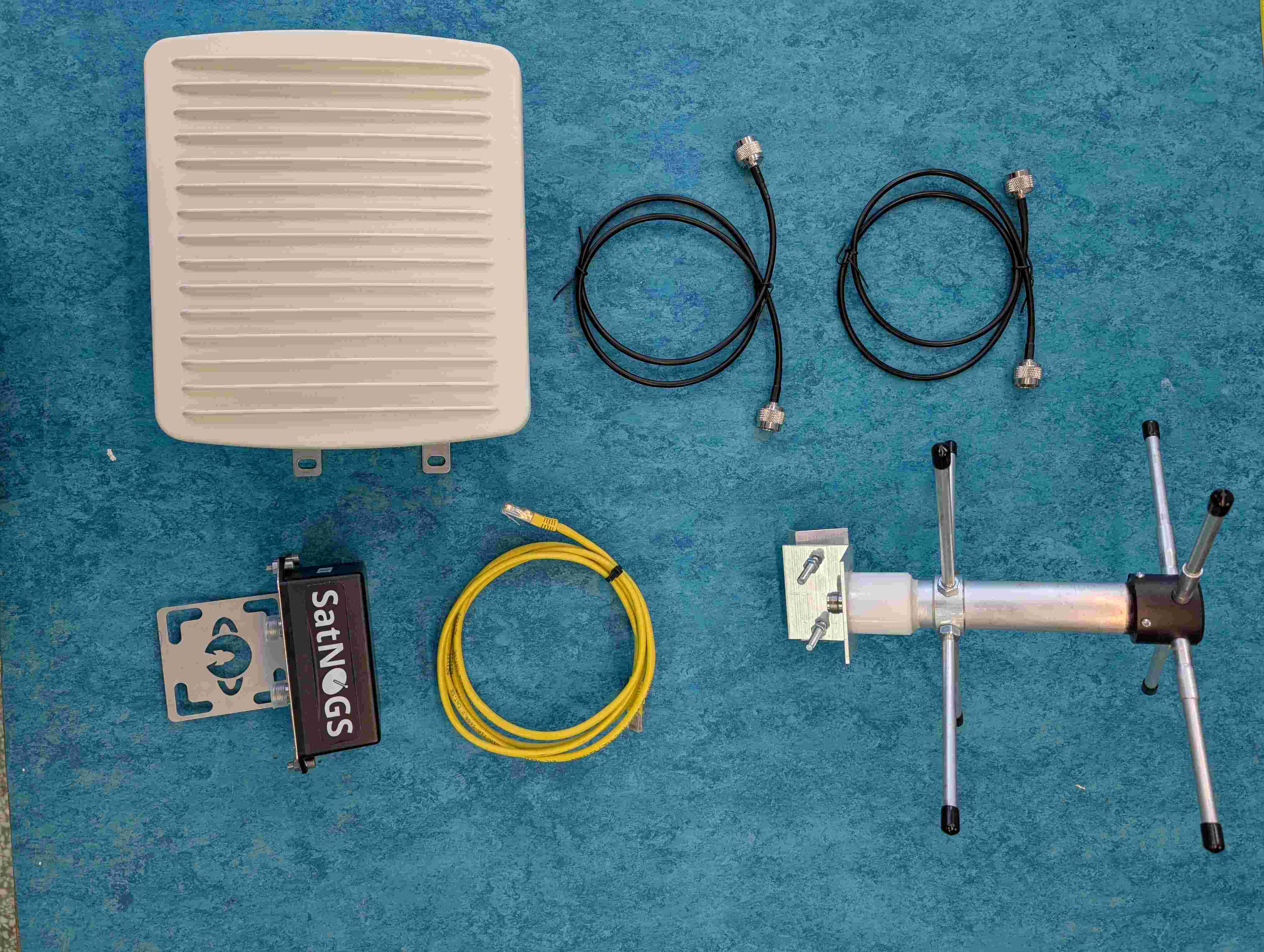
Parts
Assembled Enclosure
RF Cable (Enclosure to LNA)
RF Cable (LNA to Antenna)
Low Noise Amplifier
Ethernet Cable
Antenna
Power over Ethernet Injector (Ubiquiti POE-50-60W PoE++ Injector)
ZipTies
Tools
ZipTies
Hose mounting rings
Screwdriver set
Wrench Key
Find a pipe or pole to serve as a Mast or install one on your building roof.
Once the physical install location of the ground station is known, we need to figure out where the longer Ethernet cable will enter the building to get to the dedicated Ethernet port inside. Use a tape measure to make an approximation of length needed. Depending on the distance you will need to purchase a suitable Ethernet cable.
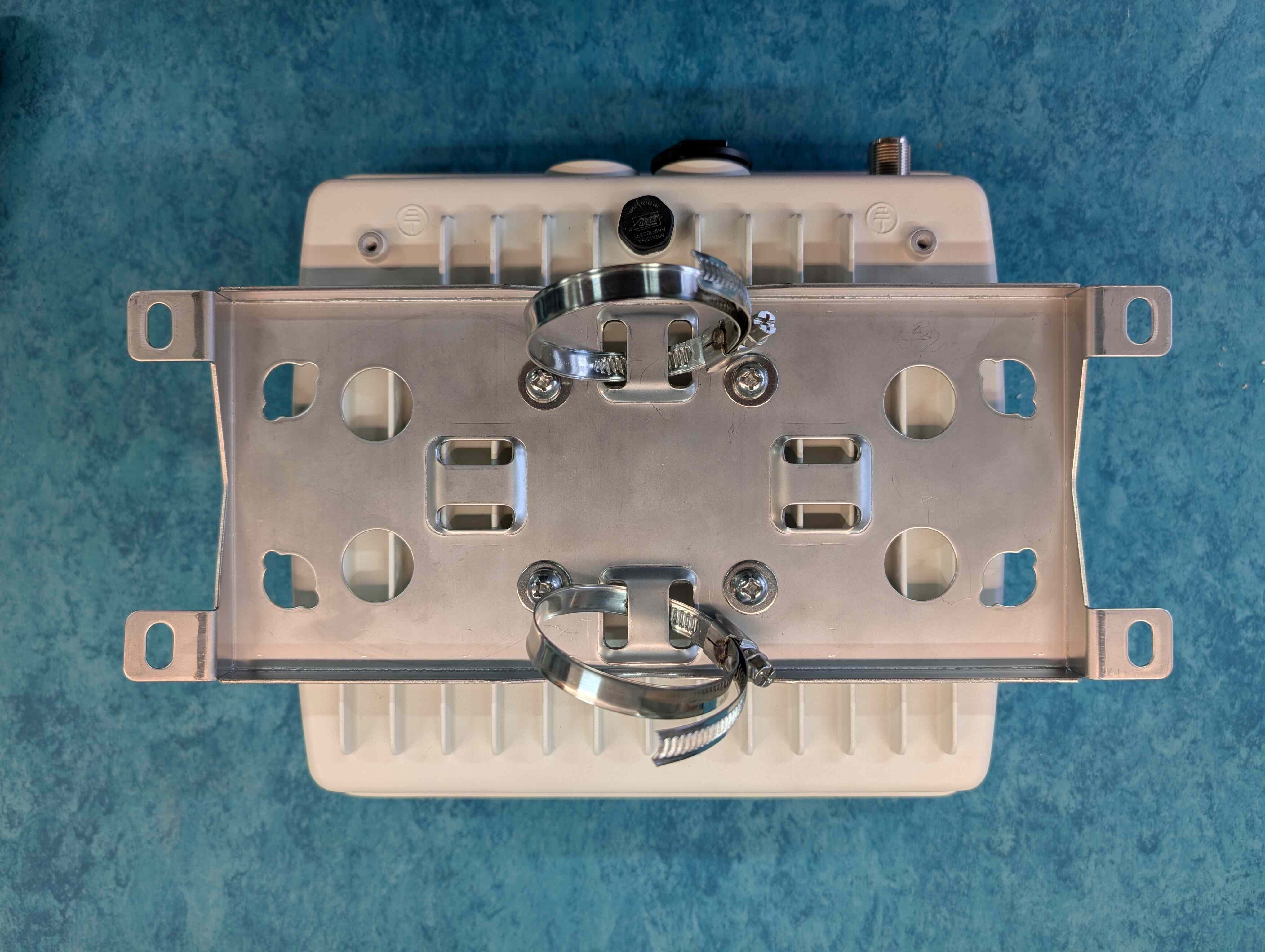
We will start the station installation firstly attaching the enclosure. Its package includes two hose clamps to attach the bracket to the pipe, install them to the back of the enclosure as in the image below .
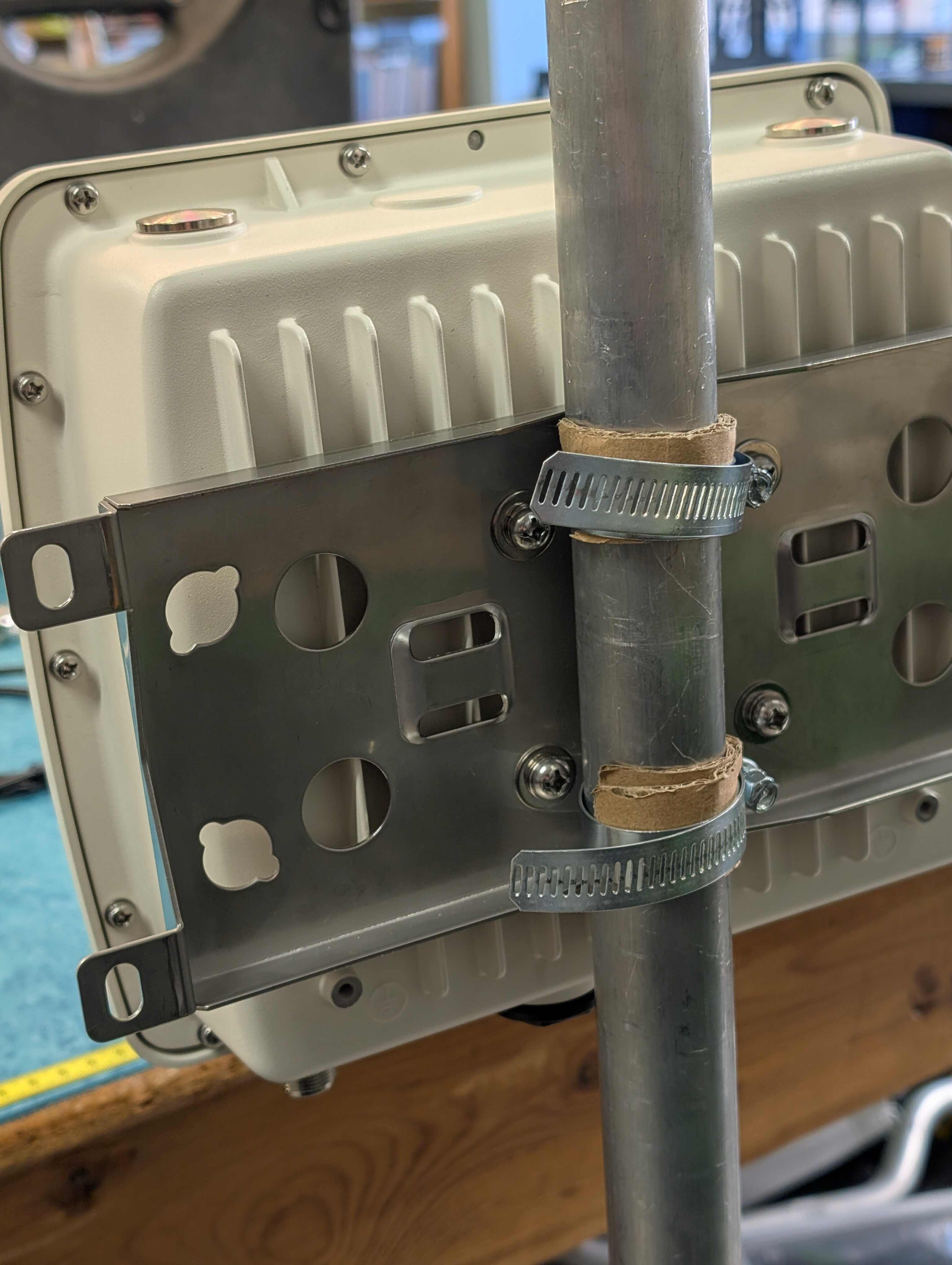
Slide the rings into the hose and tighten the unit to the pole with the rings and the screwdriver.
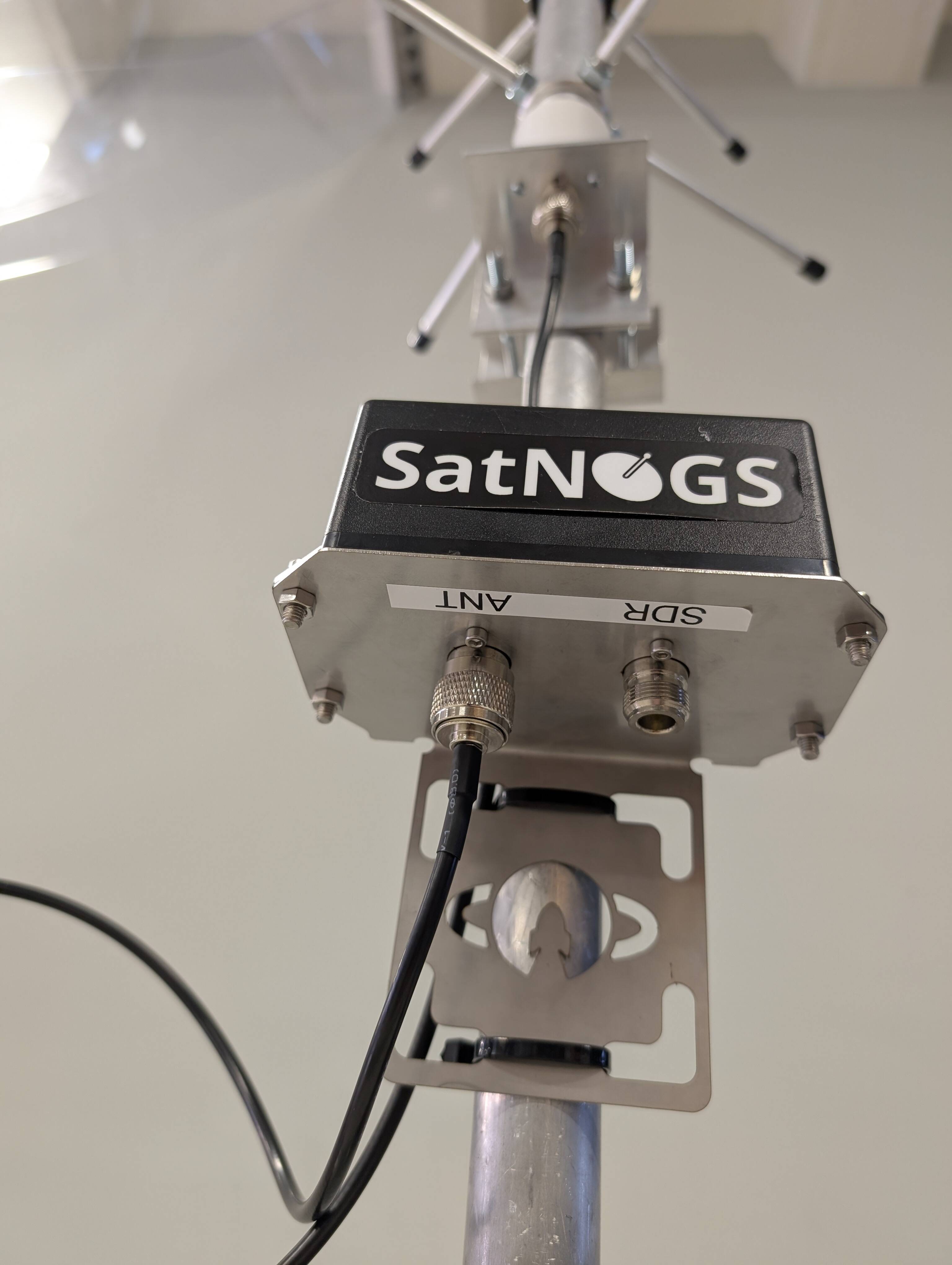
To attach the LNA two ZipTies will be used. Simply pass the ZipTies through the holes above/below of the engraved LSF logo and across the pipe like the photo below.
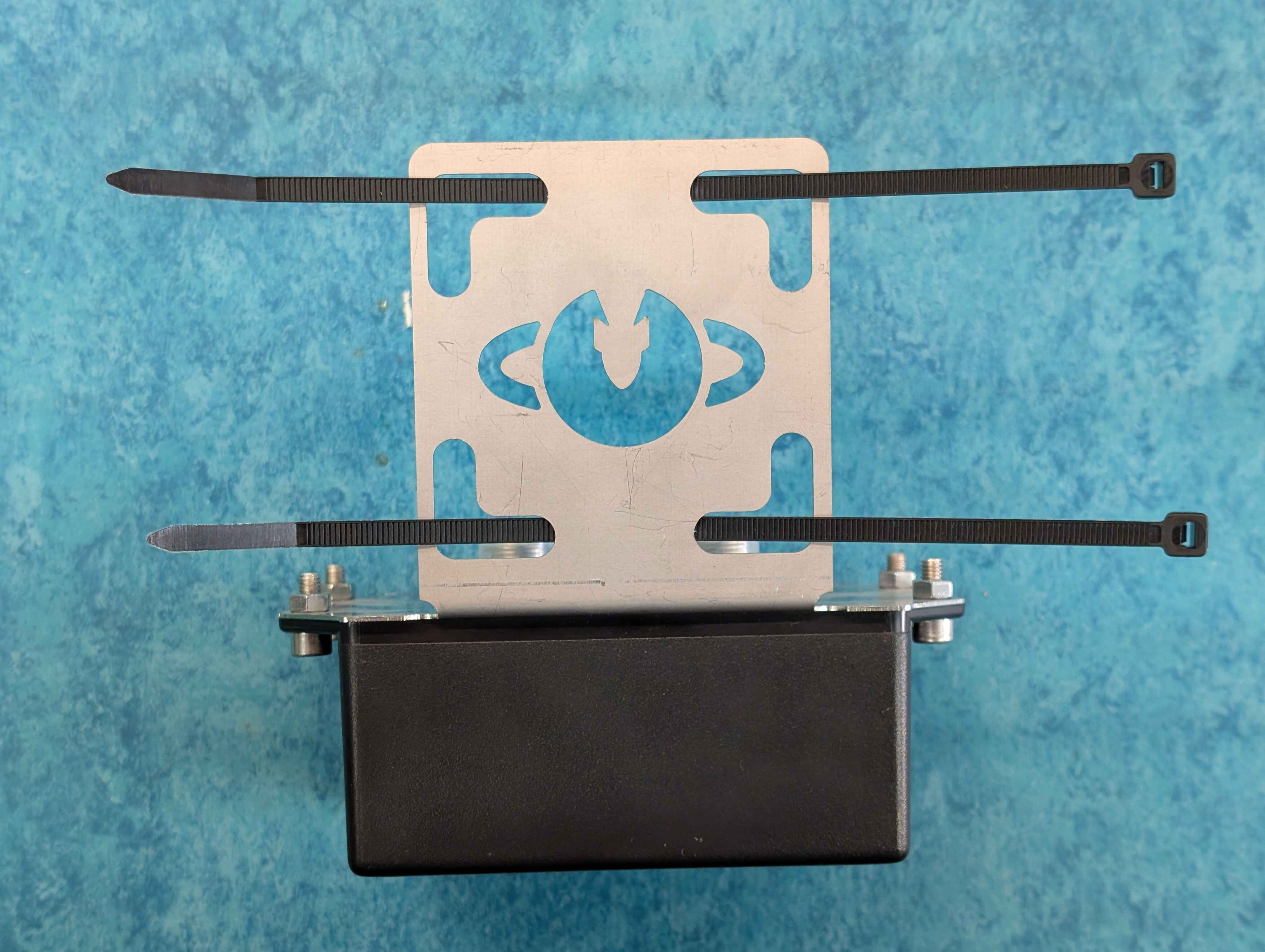
The LNA will be attached at least 10 cm higher the enclosure. Using the ZipTies secure the LNA to the pole.
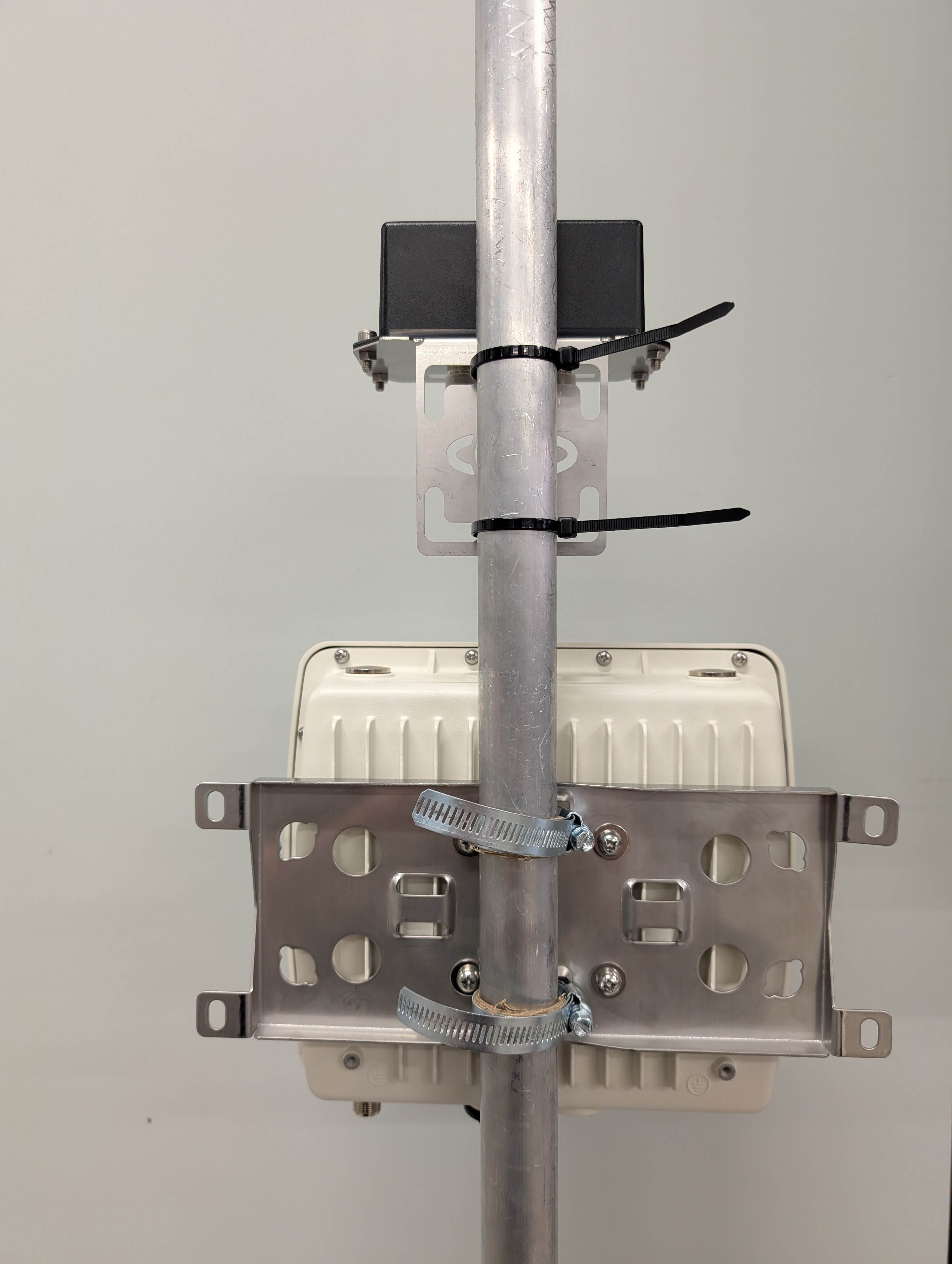
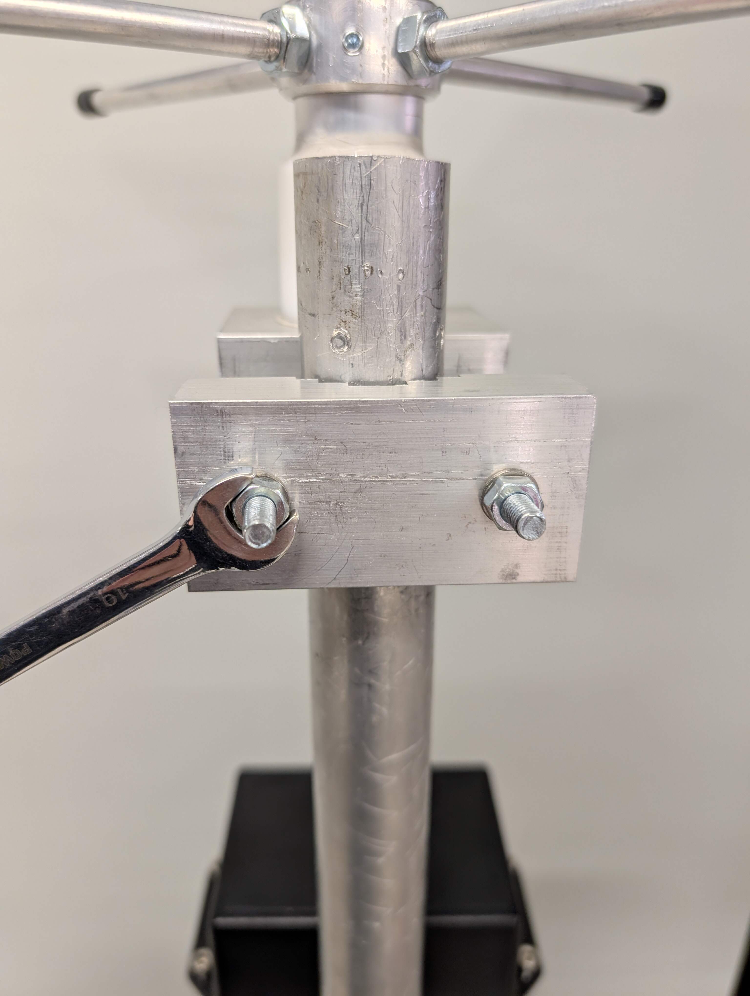
The antenna will be placed at the top of the pole. Using the mounting bracket at the bottom of the antenna and the wrench key secure it to the pole.
The LNA will be attached at least 10 cm higher the enclosure. Using the ZipTies secure the LNA to the pole.
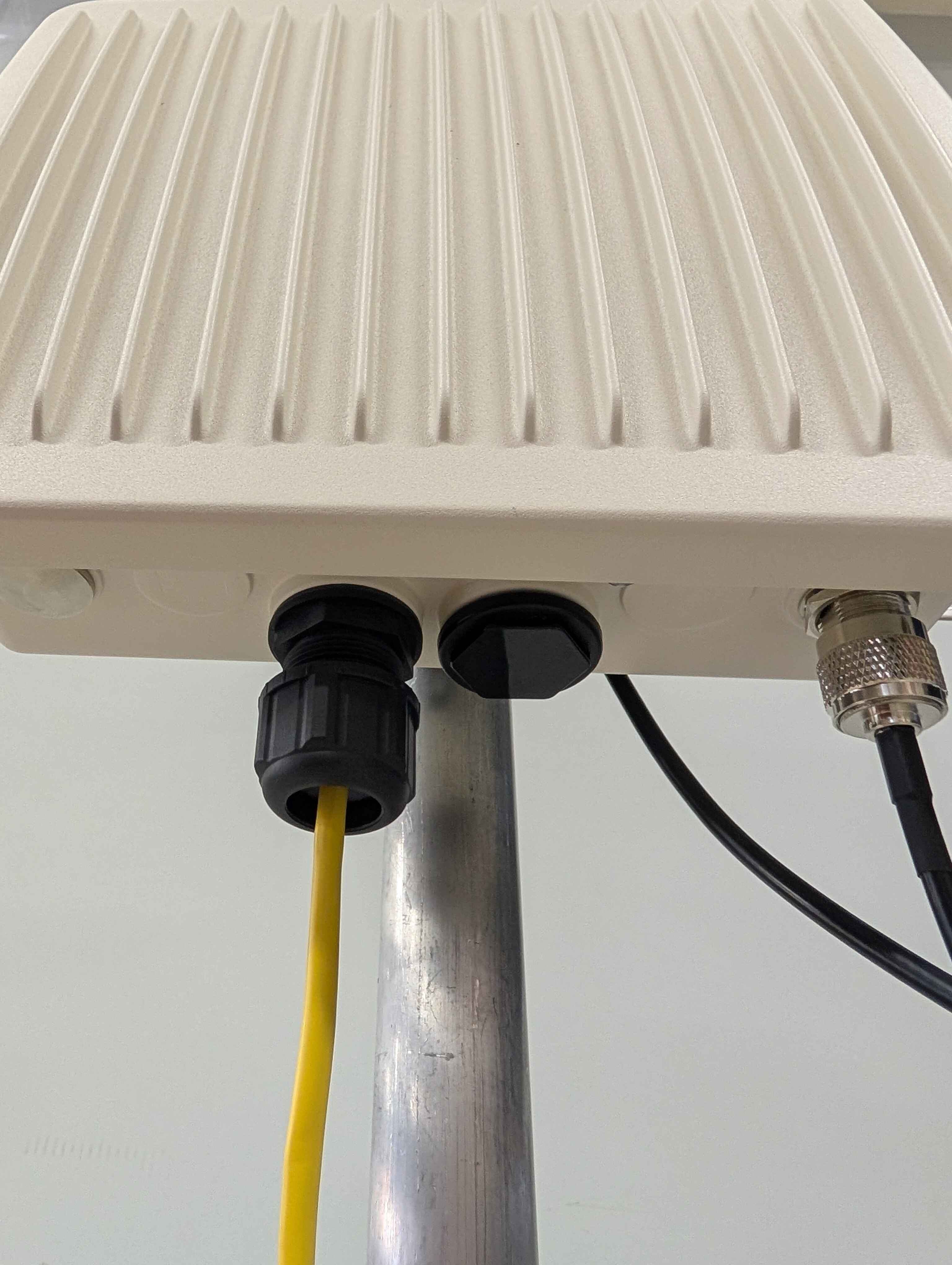
Now that the three parts of the station are placed we proceed with the cabling. Using the first 1 m N type to N type cable we connect the antenna to the LNA on the connector with right connector.
Using the second 1 m N type to N type cable we connect the second LNA connector to the bottom of the enclosure.
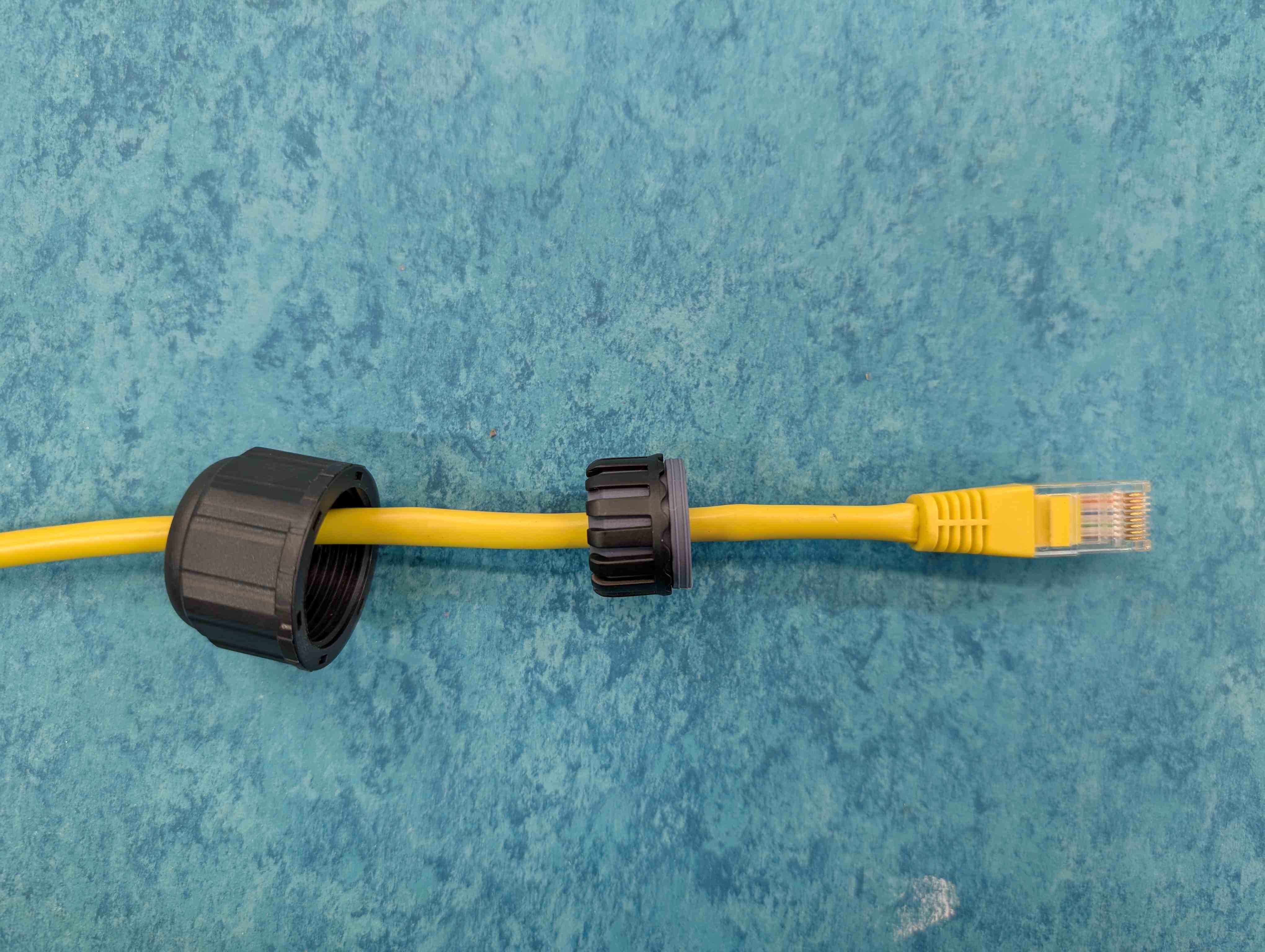
Unscrew and disassemble all parts of the UTP Enclosure Connector (Part 10) that are outside of the Enclosure. Take one end of the Ethernet Cable and feed it through the round end of the plastic cap screw. Put the split rubber washer on the Ethernet Cable between the plastic cap screw and the jack.
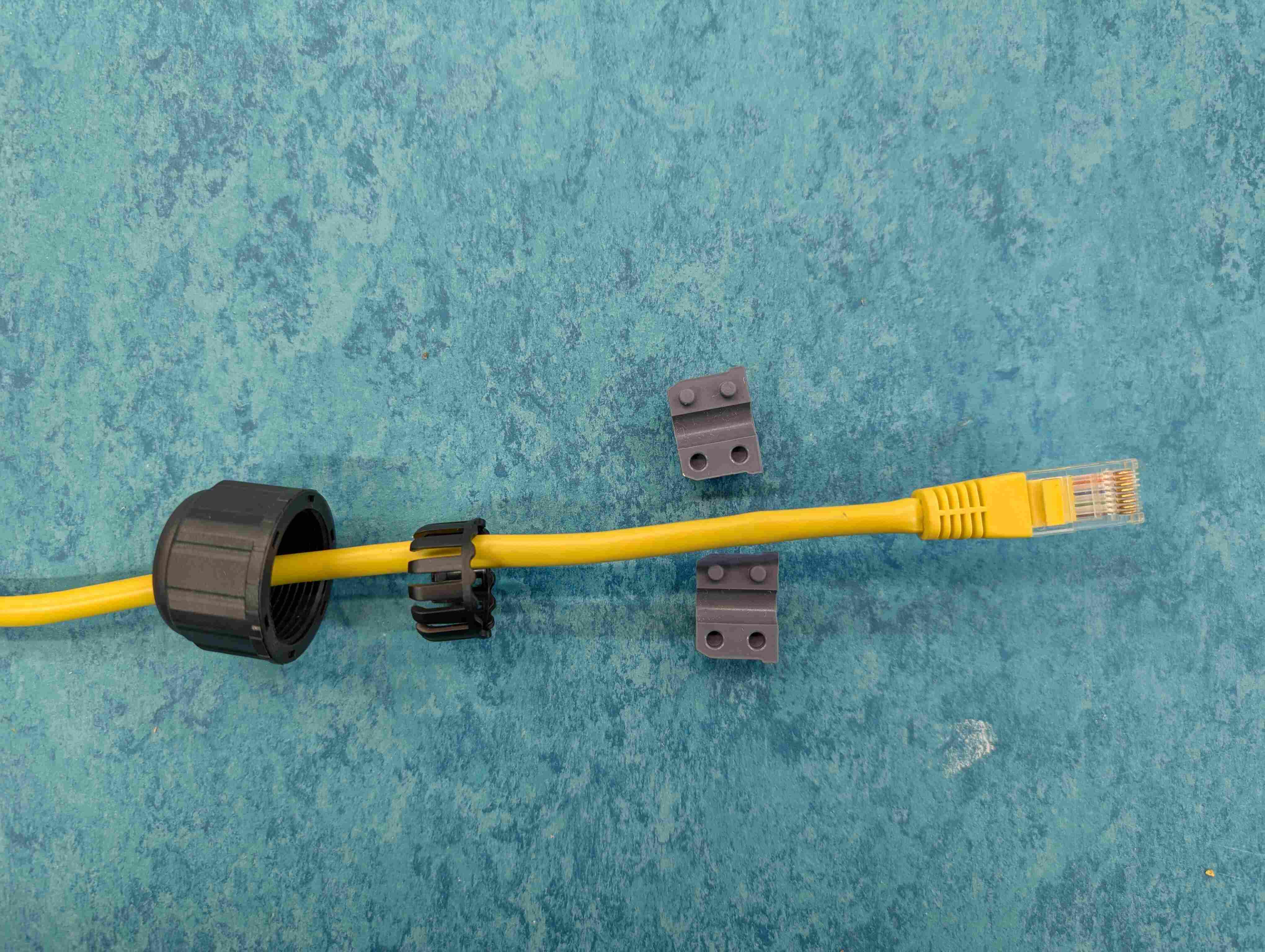
Push down on the Ethernet jack’s locking pin and push it through the narrower end of the last plastic piece. This is a tight fit, and it will feel like you really have to push it through once you get it started.
Plug the Ethernet Jack into the receptacle connected to the Enclosure.
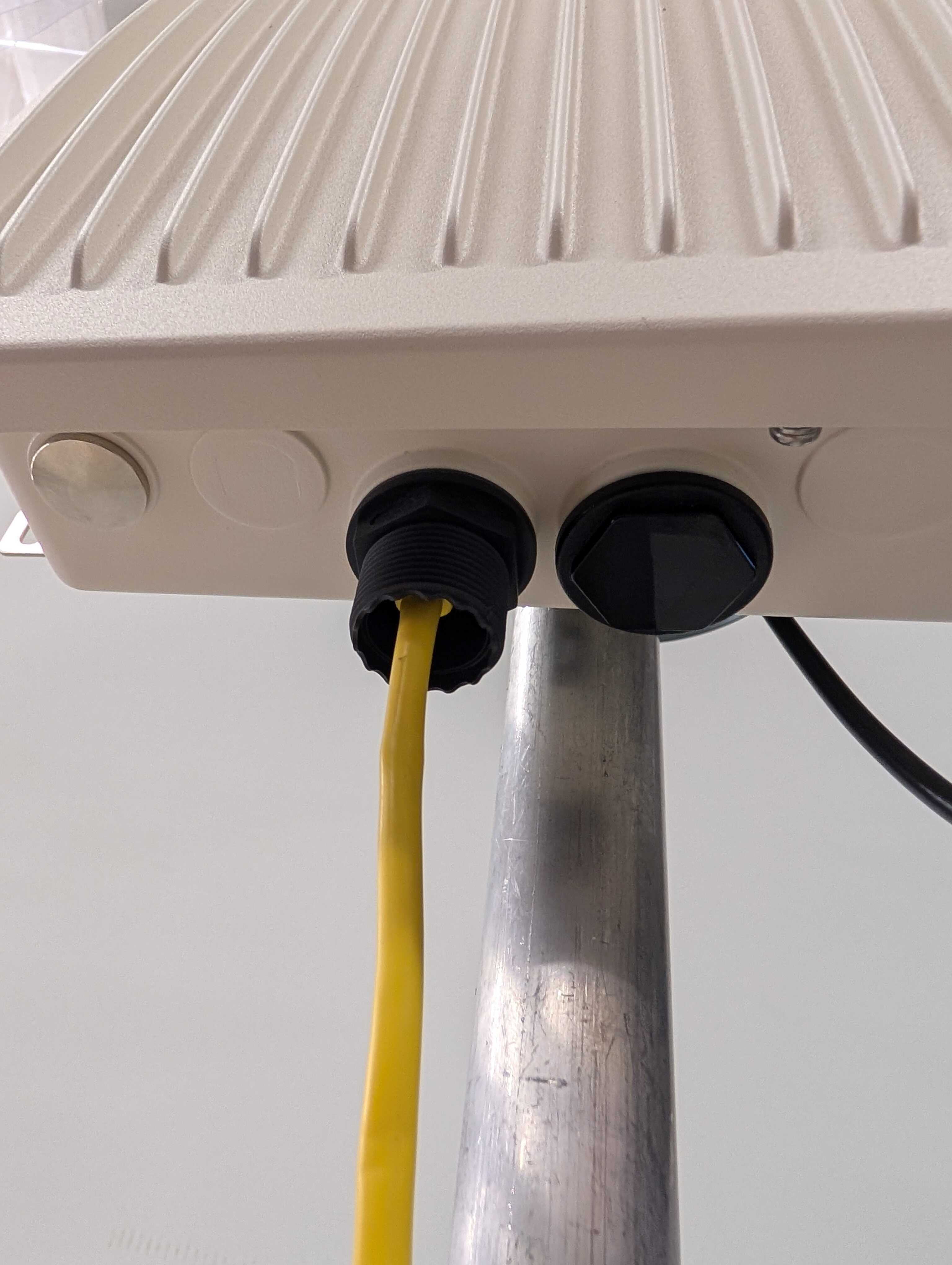
Screw the cup to seal the Ethernet cable to the enclosure.
Plug in the other end of the long Ethernet Cable to the jack on the POE Injector marked with “POE”. Plug the short Ethernet Cable (2 meters) into the “LAN” jack.
Connect the POE Injector to power and plug in the other end of the short Ethernet Cable to the appropriate port on your network.
Connecting the Station to SatNOGS network
Parts - -
Tools - -
Power on your laptop (Tool 8). Click the magnifying glass in the upper-right corner, type in Terminal, and press Return.
In terminal type this command to log in to your Pi: ssh pi@xxx.xxx.xxx.xxx replacing the xxx…. with the dynamic IP address currently being used by your Pi.
When the Raspberry Pi prompts for a password, type in: raspberry and press the Return key. Note: The command line will not show you typing the password indicated by ** as is typical with websites. If you get a message about creating a SHA-256 fingerprint, type yes, and press Return again.
Type the command:
sudo nano /etc/dhcpcd.confand press the Return key to execute it.Press the down arrow until you get to a section of this file that starts with: #Example static IP configuration
Remove the # from the following lines to un-comment them:
interface eth0
static ip_address=
static routers=
static domain_name_servers=
The first line should be: interface eth0. This tells the Raspberry Pi that we are setting the static IP on the Ethernet port not the WiFi Adapter. Ask your IT staff how to set the other 3 lines. Note: the IP address should be in slash notation (for example xxx.xxx.xxx.xxx/24) To find the correct format, see: https://en.wikipedia.org/wiki/Classless_Inter-Domain_Routing#IPv4_CIDR_blocks
Double check all values, then press CTRL and O to save and then CTRL and X to exit the file.
Type the command:
sudo rebootand press the Return key to execute it.Wait 1 minute, then type: ssh pi@xxx.xxx.xxx.xxx and press Return. This time using the static IP address you just set up.
To configure the settings of the Raspberry Pi, type in the command:
sudo raspi-configand press the Return key to execute.Press the Return key to select the first option: Change User Password. Change the default password from raspberry to something more secure by following the instructions to change your password. Take precautions to remember this password. Note: the command line will not show you typing indicated by ** as is typical with websites.
Press the Down arrow key until 4 Localisation Options is selected and press the Return key to select it. From Localisation options you can change the default language, timezone, and keyboard layout. For the timezone, choose None of the above and then pick UTC to set your station to Coordinated Universal Time, which is used by SatNOGS.
Press the Right arrow key and then the Return key to go <Back>. Press the Down arrow key a few times followed by the Return Key to choose Advanced Options. Select the first option to Expand the File System. When done return to the main menu by pressing the Right Arrow key and then the Return key to go <Back>.
Press the Right arrow key, to select <Finish>, and press Return. Type the command:
sudo rebootand press Return again.Wait 1 minute, then type: ssh pi@xxx.xxx.xxx.xxx replacing the X’s with the static IP address you set up for the Pi. Enter your new strong password when prompted
Type the command
sudo satnogs-setupfollowed by the Return key. A gray box with options on a blue background should appear. We will configure this after the ground station is installed. All we have to check now is that this command brings up the configuration client. Press the Right arrow key twice to select Exit and press Return.Type the command:
sudo shutdown -h nowfollowed by the Return key. Wait a few seconds, and then disconnect the long Ethernet Cable from the POE injector.
Post Installation
Parts - -
Tools - -
Go to the SatNOGS network at https://network.satnogs.org/
Click “Sign Up/Log in” in the upper-right, choose sign-up, and complete the registration form.
From your Dashboard, click the “+ Add Ground Station” button.
Fill out the ground station form with the following information:
Latitude/Longitude: Use https://www.latlong.net/ to find your coordinates
Altitude: Use https://www.whatismyelevation.com/ (enter in meters)
Image: Add a photo of your installed ground station
Min. Horizon: Estimate based on your location (15 degrees is typical for rooftops with minimal obstructions)
Target Utilization: Choose 100%
Antenna Type: Choose Eggbeater
Frequency Range: Choose 430.000 MHz-440.000 MHz (UHF)
Click “Submit” when complete.
Click your user icon in the upper-right and return to your Dashboard. Keep this page open—you’ll need to copy your API Key in a later step.
Open Terminal on your computer. Connect to your Raspberry Pi with the command: ssh pi@xxx.xxx.xxx.xxx (replace xxx.xxx.xxx.xxx with your Pi’s static IP address). Log in with your Pi password.
Run the command:
sudo satnogs-setupand select “Basic configuration” by pressing Return.Return to your web browser. From your SatNOGS Network Dashboard, click the “API Key” button. Copy the API Key from the popup window. Important: Never share your API Key, as it compromises your ground station’s security. If accidentally shared, contact support for a new key.
Switch back to Terminal. Press Return to enter the API Key field, paste your API Key, and press Return to save.
Navigate to SATNOGS_SOAPY_RX_DEVICE (Down arrow + Return), enter driver=lime, and press Return to save.
Navigate to SATNOGS_ANTENNA, enter LNAW, and press Return to save.
Navigate to SATNOGS_RX_SAMP_RATE, enter 2e6, and press Return to save.
Return to your web browser and open your ground station page from your Dashboard. You’ll need to copy information from this page for the remaining Basic Configuration fields.
Once all Basic Configuration options are filled in, select “Back” (Right arrow + Return).
Select “Advanced configuration options” (Down arrow + Return).
Select “Radio” (Down arrow + Return).
In the Radio settings, configure the following:
SATNOGS_GAIN_MODE: Settings Field
SATNOGS_OTHER_SETTINGS: TIA=12,PGA=0,LNA=12
These settings configure the gain for the Software Defined Radio (Part 5).
Select “Back” (Right arrow + Return).
Navigate to “Debug” (Down arrow multiple times + Return).
Select “Define SatNOGS client log level,” enter
INFO, press Return to save, then select “Back.”Select “Back” again to return to the main menu.
Select “Show” to review all settings in your configuration file. Verify everything is correct, then select “Back.”
Important: Select “Apply” and press Return. The changes are not saved until you apply them.
Wait for the system to apply the settings.
Select “Exit” to finish configuration.
Type exit and press Return to log out from your Pi session.
Return to your web browser and refresh your ground station page. If configured correctly, your ground station status should change from offline (red) to testing (orange).
On your ground station page, click the “Calculate Future Passes” button.
Find an upcoming satellite pass with a high success rate (mostly green bar), which indicates a higher likelihood of receiving transmissions. Click “Schedule” on the right.
On the New Observation page, click the “Schedule” button.
Wait for the scheduled observation time to pass. If successful, you’ll see a “waterfall” visualization showing the radio transmission from the satellite (see example below). If unsuccessful, try scheduling additional observations. If you consistently get blank waterfalls, refer to the SatNOGS Client section in Troubleshooting.